
How to Create 3D Printable Models from Medical Scans in 30 Minutes Using Free Software: Osirix, Blender, and Meshmixer

Entry posted by Dr. Mike ·
173,619 views

Hello, it's Dr. Mike here again with another tutorial and video on medical 3D printing. In this tutorial we're going to learn how to take a DICOM-based medical imaging scan, such as a CT scan, and convert into an STL file in preparation for 3D printing. We will use the free, open-source software program Osirix to do this. Once the file is converted into STL format, we will use the free software packages Blender and Meshmixer to prepare the file for 3D bioprinting. If mastered, this material should easily allow you to make a high-quality 3D printed medical model in less than 30 minutes using free software. Expensive, proprietary software is not needed. This tutorial is designed primarily for Macintosh users since Osirix is a Macintosh-only program. If you use Windows or Linux, please stay tuned for my upcoming tutorial on using free, open-source 3D Slicer to create medical and anatomic models.
If you haven't already done so, please see my tutorial on selecting the best medical scan to create a 3D printed model. If you start your 3D printed model project with the wrong kind of scan, your model will not turn out well. Selecting the right kind of scan is critically important and will save you a lot of frustration. Take a few minutes to look over this brief tutorial. It will be well worth your time.
Before you start, DOWNLOAD THE FILE PACK that accompanies this video so you can follow along on your own computer. When you finish the tutorial, you will have your very own 3D printable skull STL file. Download is free for members, and registration for membership is also free and only takes a minute.
Video 1: The video version of this tutorial. It takes you from start to finish in 30 minutes. The written version here has more detail though.
A Few Brief Definitions
What is Osirix?
Osirix is a Macintosh-only software package for reading medical imaging scans (Figure 1). There are several versions. There is an FDA-approved version designed for doctors reading scans in clinics and hospitals, a 64-bit version for research and other nonclinical activities, and a free, 32-bit version. The main difference between the free 32-bit version and the paid 64-bit version is the 64-bit version can open very large imaging studies, such as MRI exams with thousands of images. The 32-bit version is limited to about 500 images. Additionally, there is a performance boost with the paid versions. If you are just getting into 3D bioprinting, the free, 32-bit version is a great place to start. It can be downloaded at the Osirix website here.
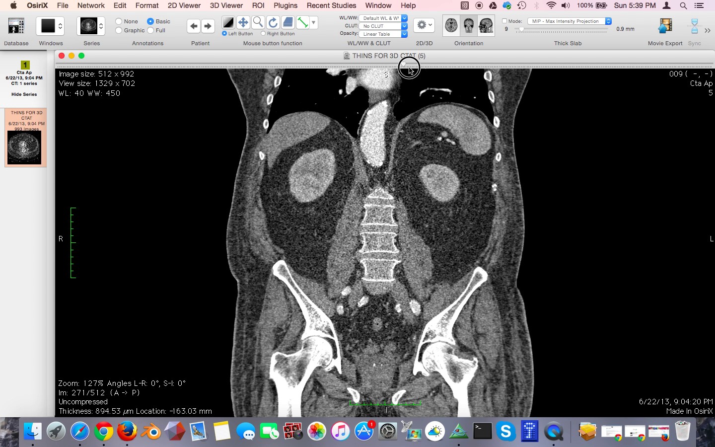
Figure 1: An example of Osirix being used to read a CT scan.
What is DICOM?
DICOM stands for Digital Imaging and Communications in Medicine. It is the standard file format for most medical imaging scans, such as Computed Tomography (CT), Magnetic Residence Imaging (MRI), ultrasound, and x-ray imaging studies.
What is STL?
STL, or STereoLithography format , is an engineering file format created by 3D Systems for use with Computer Aided Design software (CAD). The file format is primarily used in engineering, and has become the standard file format for 3D printing.
The Problem with 3D Printing Anatomic Structures
The major problem with trying to 3D print anatomic structures from medical scans is that the medical scan data is in DICOM format and 3D printers require files in STL format. The two formats are incompatible. There are very expensive, proprietary software packages that can perform the conversion between DICOM and STL. A little-known secret is that this can also be done using free, open-source software. Osirix is the best solution for Macintosh. 3D Slicer is the best solution for Windows and Linux. I will discuss 3D Slicer in an upcoming tutorial.
If you haven't already, please download the DICOM data set we will be using in this tutorial. This data set is from a high quality CT scan of the brain and skull. It has been anonymized and has been put in the public domain for research by the US National Cancer Institute. Also included with the download packet are other files we will use for this tutorial, including the final STL file of the skull. The download is free for members, and registration for membership is also free and only takes a minute.
From the Macintosh Finder navigate to the folder with the downloaded tutorial file pack and double-click on the file TCGA-06-5410 sharp.zip.
Opening the CT scan with Osirix
Open Osirix. From the File menu, click Import, Import Files. Click Open. (Figure 2)
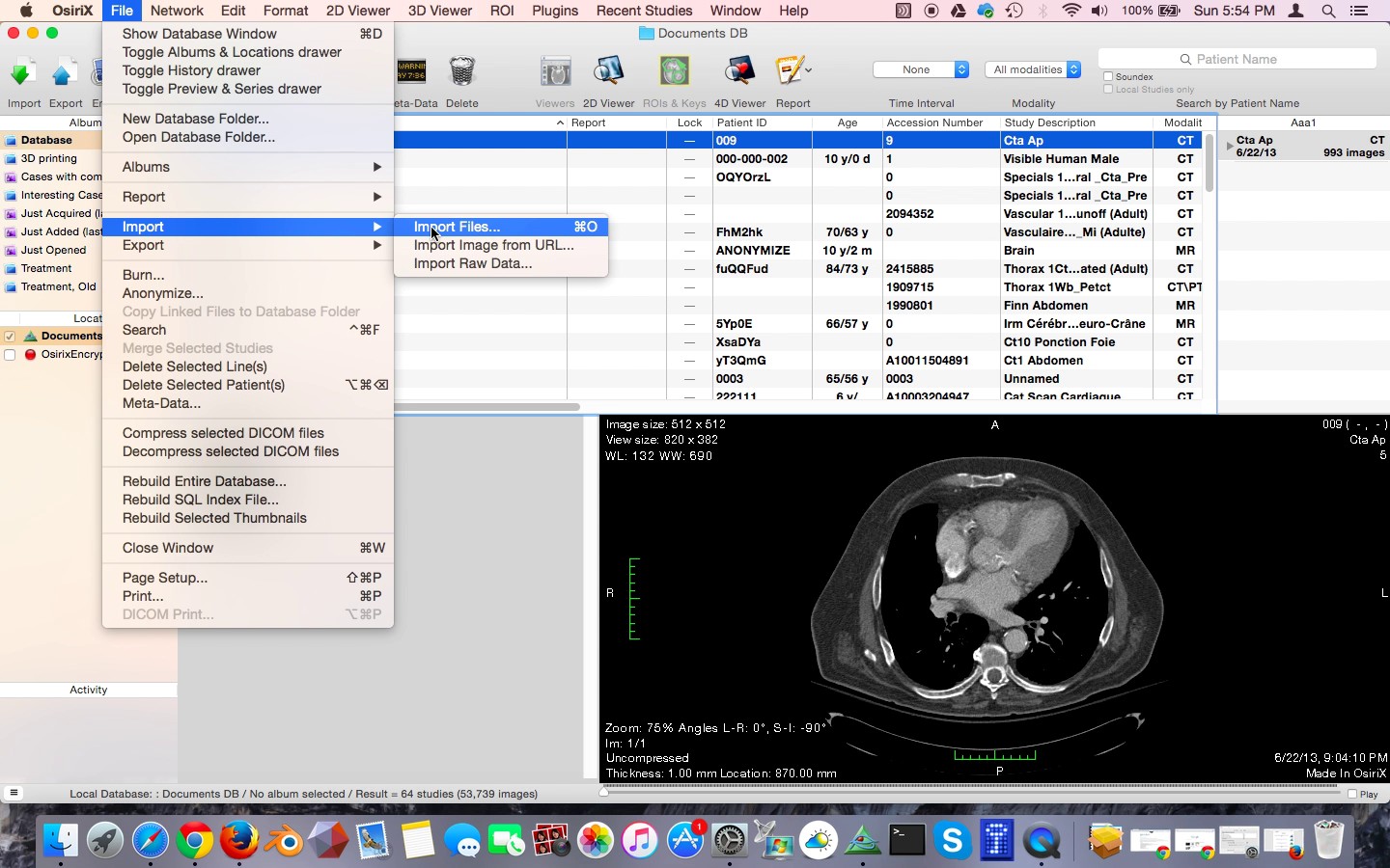
Figure 2: Importing the CT scan into Osirix
Navigate to the folder that contains your DICOM data set. Click the Open button.
Osirix will ask you if you want to copy the DICOM files into the Osirix database, or only copy the links to these files. Click "Copy Files."
Osirix will begin to copy the files into the database. A progress bar will be shown on the lower left-hand corner. When the data is imported you'll see a small orange circle with a "+" in it. This orange circle will eventually go away when Osirix is finished analyzing the study, but you can open the study and work with it while Osirix does some cleanup postprocessing. Left click on the study.
You will see an icon with a label "FIDUCIALS 1.0 SPO cor, 216 Images." This is a CT scan of the head with coronal slices at 1 mm intervals. Double-click on this icon, Figure 3.
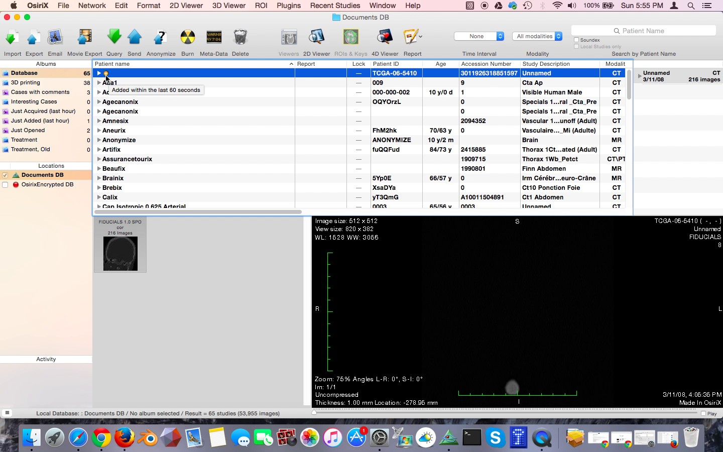
Figure 3: The study when opened
Osirix will remind you that you're not supposed to be using it for diagnostic scan reading on real patients unless you are using the more expensive FDA approved version, Osirix MD we're just using it to create a 3D model, so click "I agree."
At this point, the study will load. Use the mouse wheel or the bar on the top of the screen to scroll.
You can see that this is a pretty decent CT scan of the head for 3D printing. There is not much artifact from metallic dental implants because the maxilla and mandible have been cut off.
Segmenting the bony skull and creating a new series
We can measure the density of the bony structures using the Region Of Interest or ROI tool. This measures the Hounsfield density, or CT density, of the target area. Select the oval tool from the drop-down menu, Figure 4.
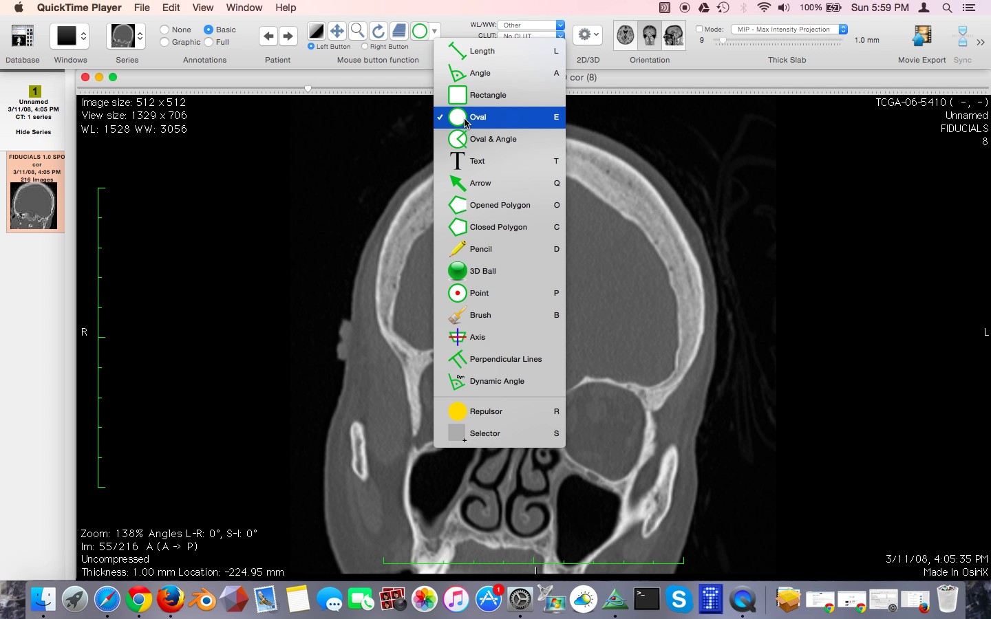
Figure 4: The ROI tool.
Choose a region of bone using the oval tool. You will see that information about this region is displayed. What we are interested in is the mean density, which in this case is 1753.194, Figure 5.
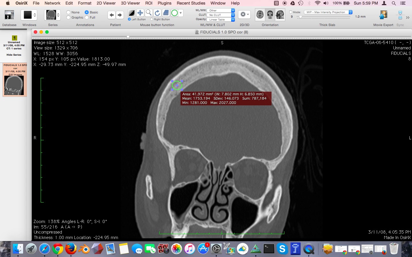
Figure 5: Density measurement using ROI tool. The mean density is 1753.194, as shown in maroon field.
Use the ROI tool to select another region in the brain. You will see that the mean attenuation, or density, is much less, in this case 1059.137, Figure 6.
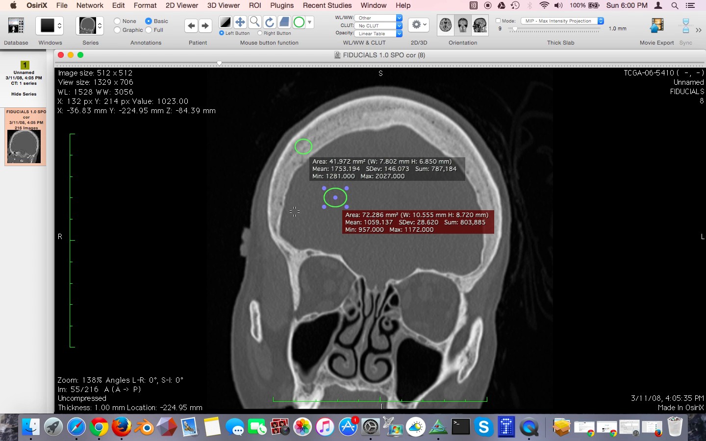
Figure 6: Density measurement of the brain tissue.
Finally, use the oval tool to choose an area in the air adjacent to the head. You can see that the mean attenuation of this region is 38.514, Figure 7.

Figure 7: Density measurement of air.
In this scan the Hounsfield attenuation numbers have been shifted. In a typical scan, air measures about -1000, soft tissue between 30 and 70, and bone typically greater than 300. In this scan those numbers have been increased by 1000. Since we were thorough enough to check the Hounsfield attenuation before moving on, we can easily correct for this shift.
Under ROI menu select Grow Region 2D/3D Segmentation, Figure 8.
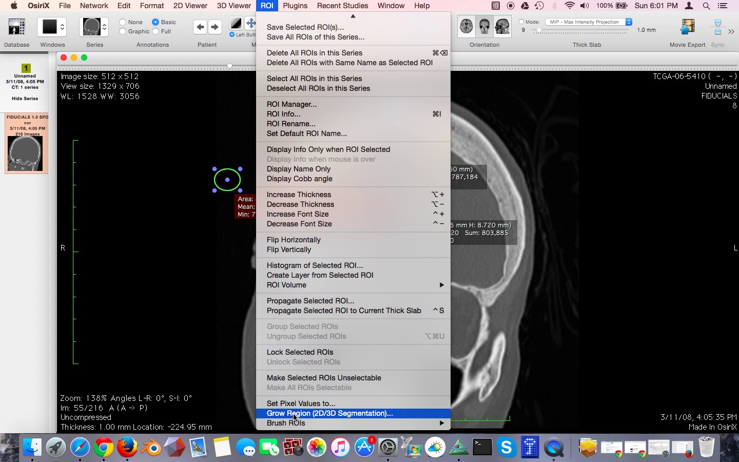
Figure 8: The Grow Region tool
In the Segmentation Parameters window that pops up, set the following:
Lower Threshold 1150
Upper Threshold 3000.
Generate a new series with:
Inside pixels 1000
Outside pixels 0
Be sure to check the checkbox next to the Set Inside Pixels, and Set Outside Pixels fields, Figure 9.
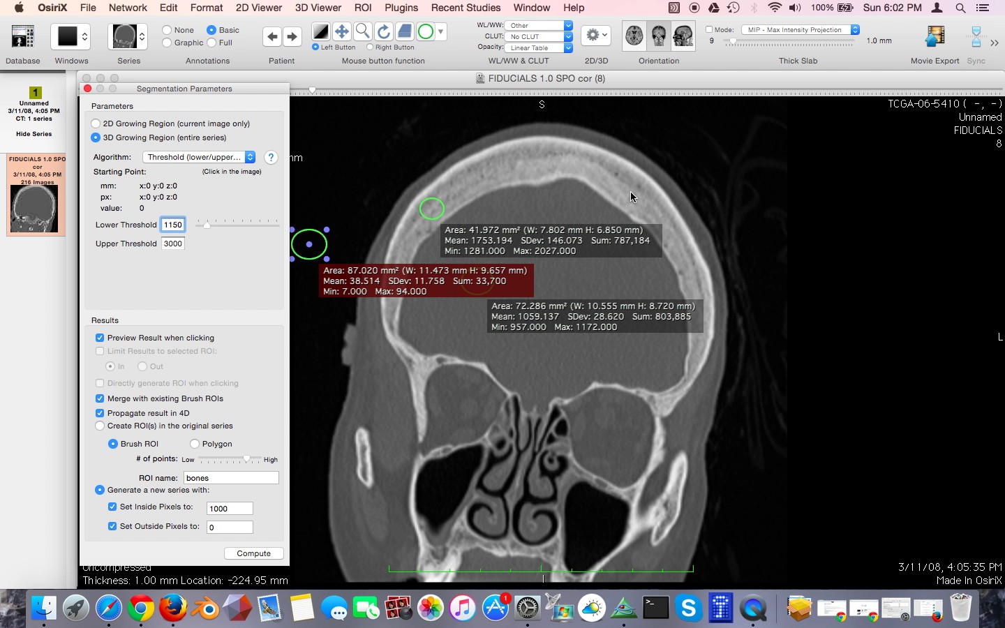
Figure 9: Setting up the Segmentation Parameters window.
Next, make sure you select a starting point for the algorithm. Left click on one of the skull bones. Green crosshairs will show. All of the bone that is contiguous with point you clicked will now be highlighted in green, Figure 10.

Figure 10: Setting the starting point for segmentation. The target region turns green.
Click the Compute button
Osirix will generate a new series with the bones being a single white color with a value of 1000, and everything else being a black color with a value of zero, Figure 11. Creating a separate series just for 3D printing purposes is the secret to getting good 3D models from Osirix. Trying to generate a 3D surface model directly from the 3D Surface Rendering function underneath the 3D Viewer menu is tempting to use, however it will not work well for generating STL files. This is not obvious, and the source of much frustration for beginners trying to use Osirix for 3D printing.
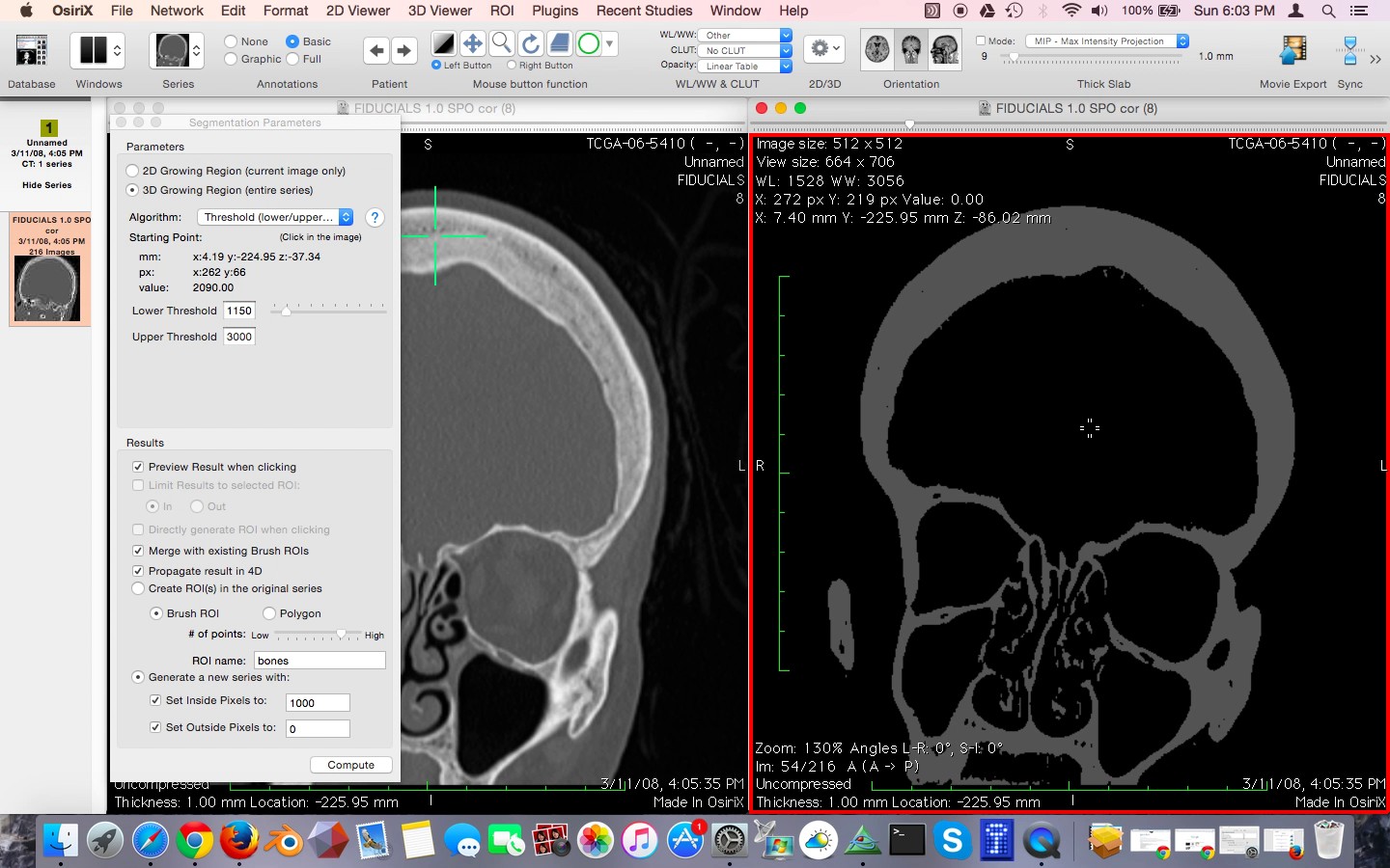
Figure 11: The new bitmapped series shown on right of screen. This series has only two colors, black and white. It is idea for conversion to and STL surface model.
Generating an STL file from the new bitmapped series
Now we are ready to create our 3D surface model. Make sure that your new bitmapped series is highlighted. Click on the 3D viewer menu and select 3D Surface Rendering, Figure 12. Leave the settings set to their default values. Click OK as shown in Figure 13.
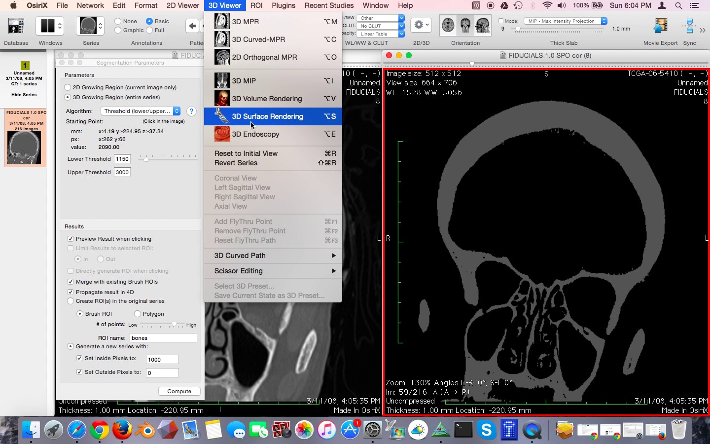
Figure 12: Selecting 3D Surface Rendering
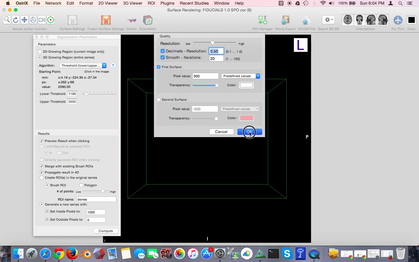
Figure 13: Setting 3D surface rendering settings
Osirix will then think for a few moments as it prepares the surface. You can see that a relatively good approximation of the skull has been generated. Use of the left mouse button to rotate the 3D model.
Next were going to export the 3D surface model to an STL file. Click Export 3D-SR and choose Export as STL as show in Figure 14. Type the file name "skull file." Click Save.
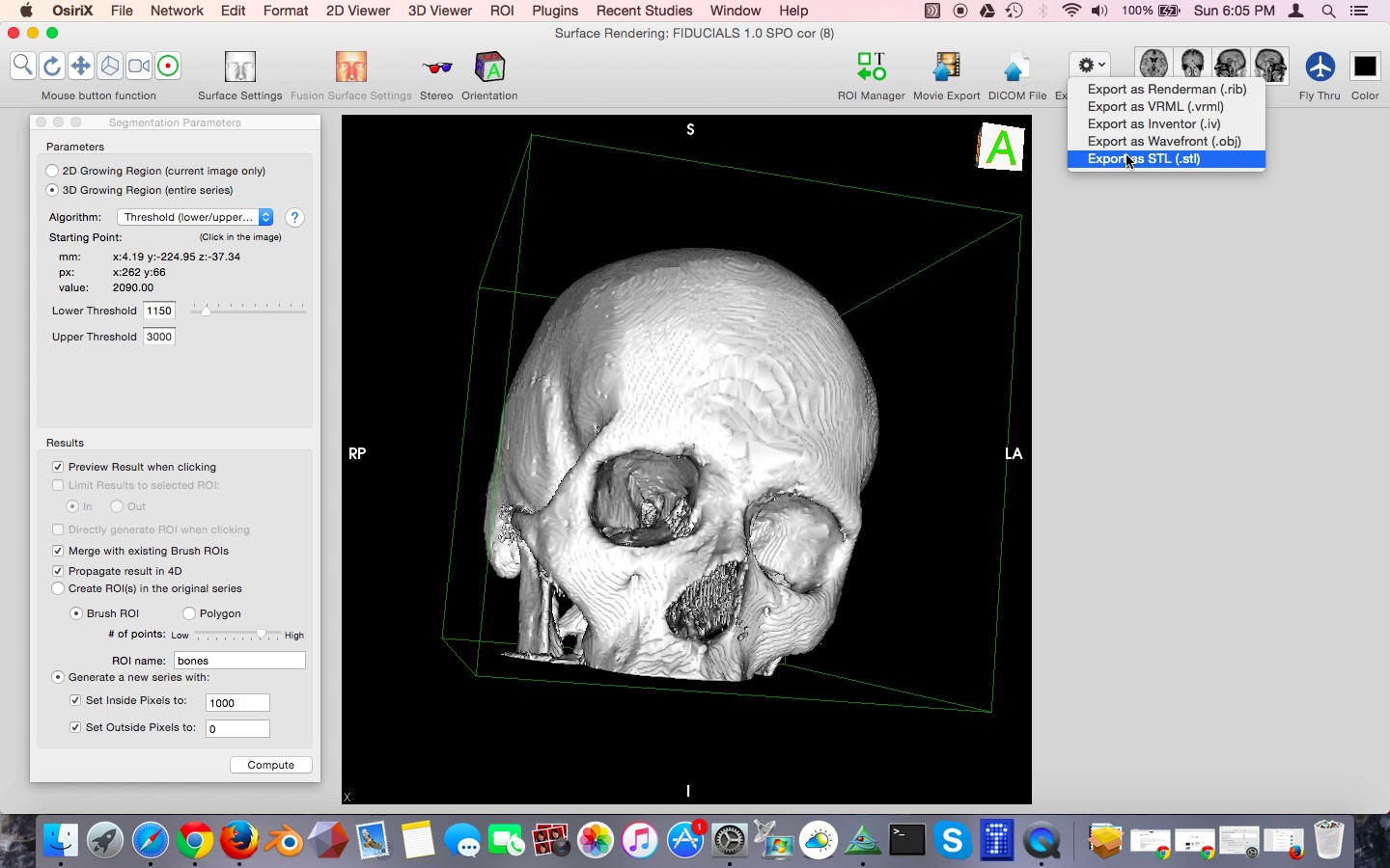
Figure 14: Exporting model to STL file format.
Cleaning up the 3D model in Blender
You can see from the 3D rendering that there are many small islands of material that have been included with the STL file. Also, the skull has a very pixelated appearance. It does not have the smooth surface that would be expected on a real skull. In order to fix these problems, we're going to do a little postprocessing in Blender, a free open-source 3D software program.
If you don't already have Blender on your computer, you can download it free from blender.org. Blender is available for Windows, Macintosh, and Linux. Select your operating system, preferred installation method, and download mirror.
Once Blender is installed on your computer, open it. In the default scene there will be a cube. We don't need this. Right click on the cube to select it. Then delete it using the delete key on a full keyboard or the X key on a laptop keyboard. Blender will ask you to confirm you want to delete the object. Click Delete as shown in Figure 15.
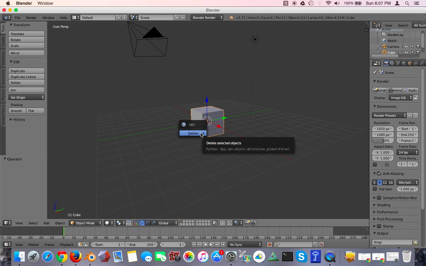
Figure 15: Deleting the default cube.
Next, we are going to import the skull STL file. From the File menu select Import, STL, as shown in Figure 16. Navigate to the skull STL file you saved from Osirix, and double-click it. Blender will think for a few seconds and then return to what appears to be an empty scene, as shown in Figure 17. Where is your skull? To find your skull, use the mouse scroll wheel to zoom out. If you zoom out far enough you will see the skull. The skull appears to be gigantic, as shown in Figure 18. This is because the default unit of measurement in the skull is 1 mm. In Blender, an arbitrary unit of measurement called a "blender unit" is used. When the skull was imported, 1 mm of real size was translated into 1 blender unit. Thus the skull appears to be hundreds of blender units large, and appears very big.
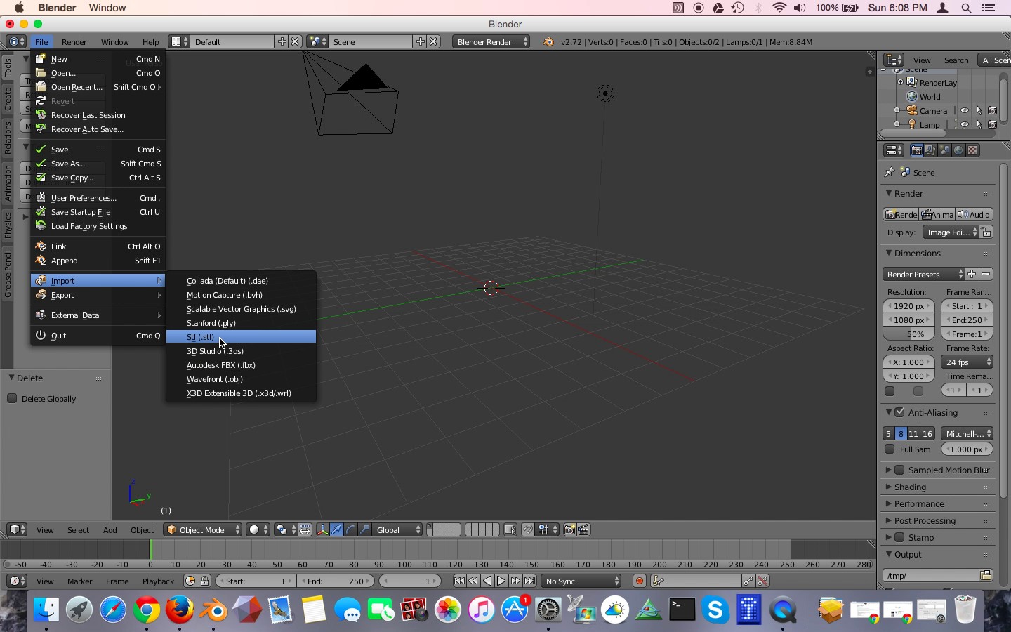
Figure 16: Importing the STL file into Blender
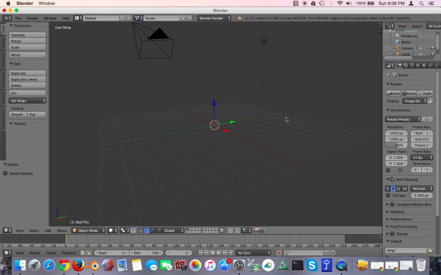
Figure 17: The "empty" scene. Where is the skull?
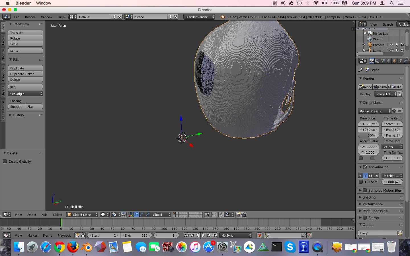
Figure 18: Zoom out and the skull appears!
The skull is also offset from the origin. We are going to correct that. Make sure that the skull is still selected by right clicking on it. If it is selected it will have a orange halo. In the lower left corner of the window click on the Object menu. Select Transform, Geometry to Origin as shown in Figure 19. The skull is now centered on the middle of the scene.
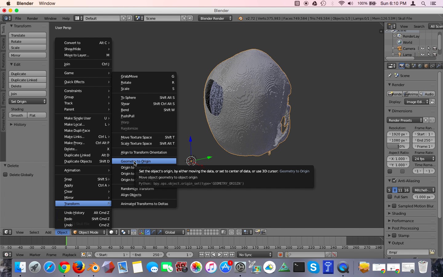
Figure 19: Centering the skull in the scene.
Deleting Unwanted Mesh Islands
First, let's get rid of the extra mesh islands. There is a menu in the lower left-hand corner of the window that says Object Mode. Click on this and go to Edit Mode, as shown in Figure 20.
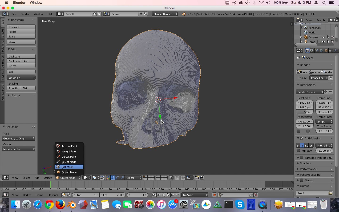
Figure 20: Entering Edit mode in Blender.
Now we are in Edit Mode. In this mode we can edit individual edges and vertices of the model. Right now the entire model is selected because everything is orange. In edit mode you can select vertices, edges, or faces. This is controlled by the small panel of buttons on the bottom toolbar. Make sure that the leftmost or vertex selection mode is highlighted and then right click on a single vertex on the model, as shown in Figure 21. That vertex should become orange and everything else should become gray, because only that single vertex is now selected, Figure 22.
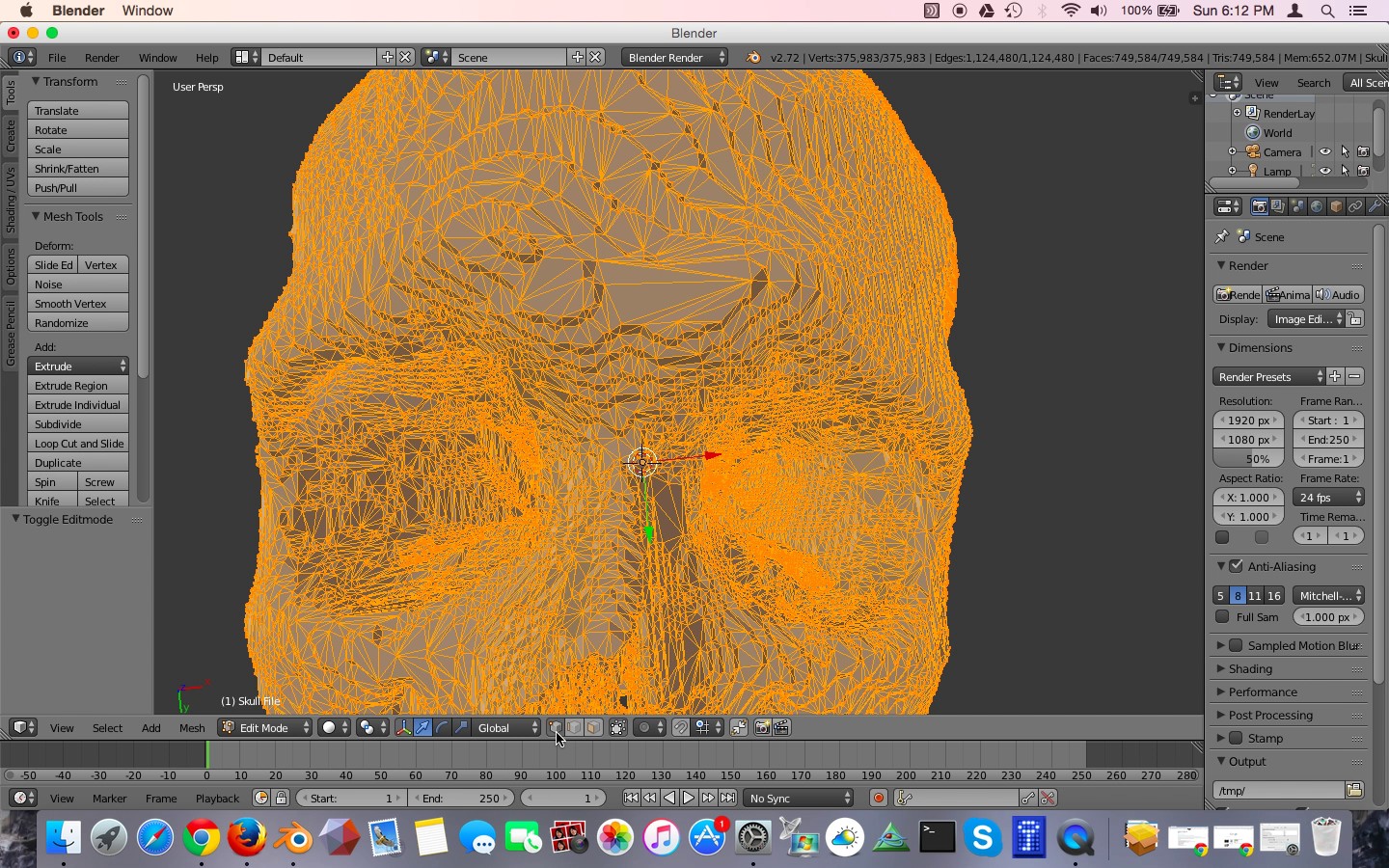
Figure 21: Vertex selection mode
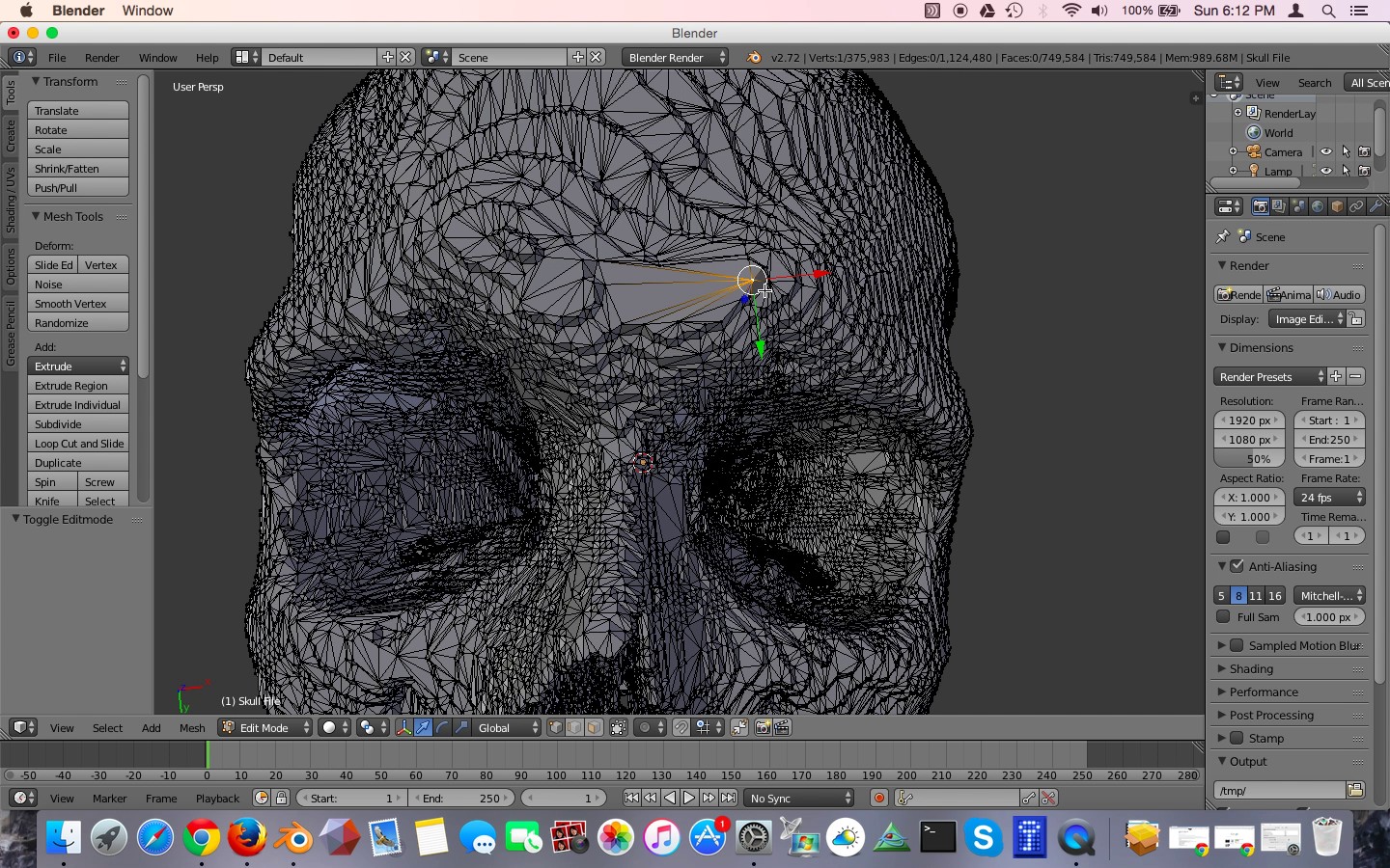
Figure 22: Select a single vertex by right clicking on it.
Under the Select menu, click Linked, as shown in Figure 23. Alternatively, you can hit Control-L. This selects every vertex that is connected to the initial vertex you selected. All the parts of the model that are contiguous with that first selection are now highlighted in orange. You can see that the many mesh islands we wish to get rid of are not selected.
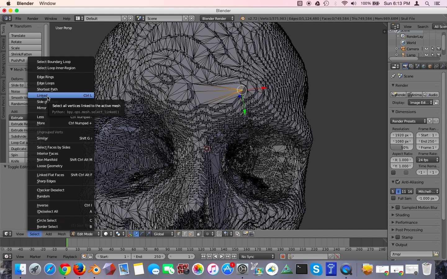
Figure 23: Selecting all linked vertices.
We are next going to invert the selection. Do this by again clicking on the Select menu and choosing Inverse, Figure 24. Alternatively, you can hit Control-I. Now, instead of the skull being selected, all of the unwanted mesh islands are selected, as shown in Figure 25. Now we can delete them. Hit the delete key, or alternatively the X key. Blender asks you what you want to delete. Click Vertices, Figure 26. Now all of those unwanted mesh islands have been deleted.
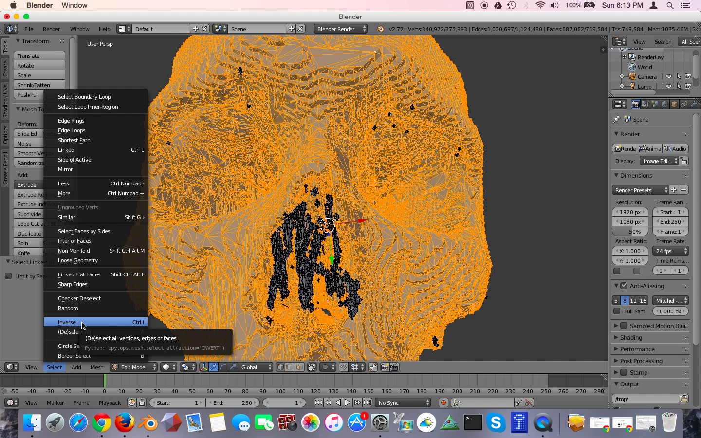
Figure 24: Inverting the selection.
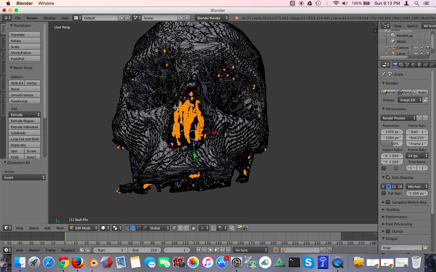
Figure 25: The result after inverting the selection. Only the unwanted mesh islands are selected!
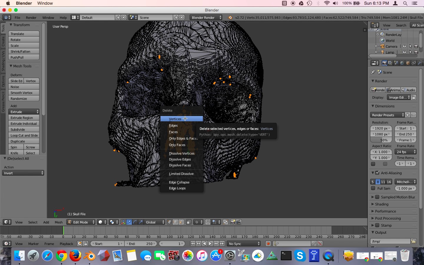
Figure 26: Deleting the unwanted mesh islands.
Repairing Open Mesh Holes
We can see that on the top of the skull there is a large hole where the skull was cut off by the scanner. Because the bone surface was cut off, Osirix left a gaping defect, Figure 27. Before 3D printing, this will have to be corrected. This is what is called a manifold mesh defect. It is an area where the surface of the model is not intact. A 3D printer will not know what to do with this, such as whether it should be filled in or left hollow. Fortunately, it is relatively easy to correct.
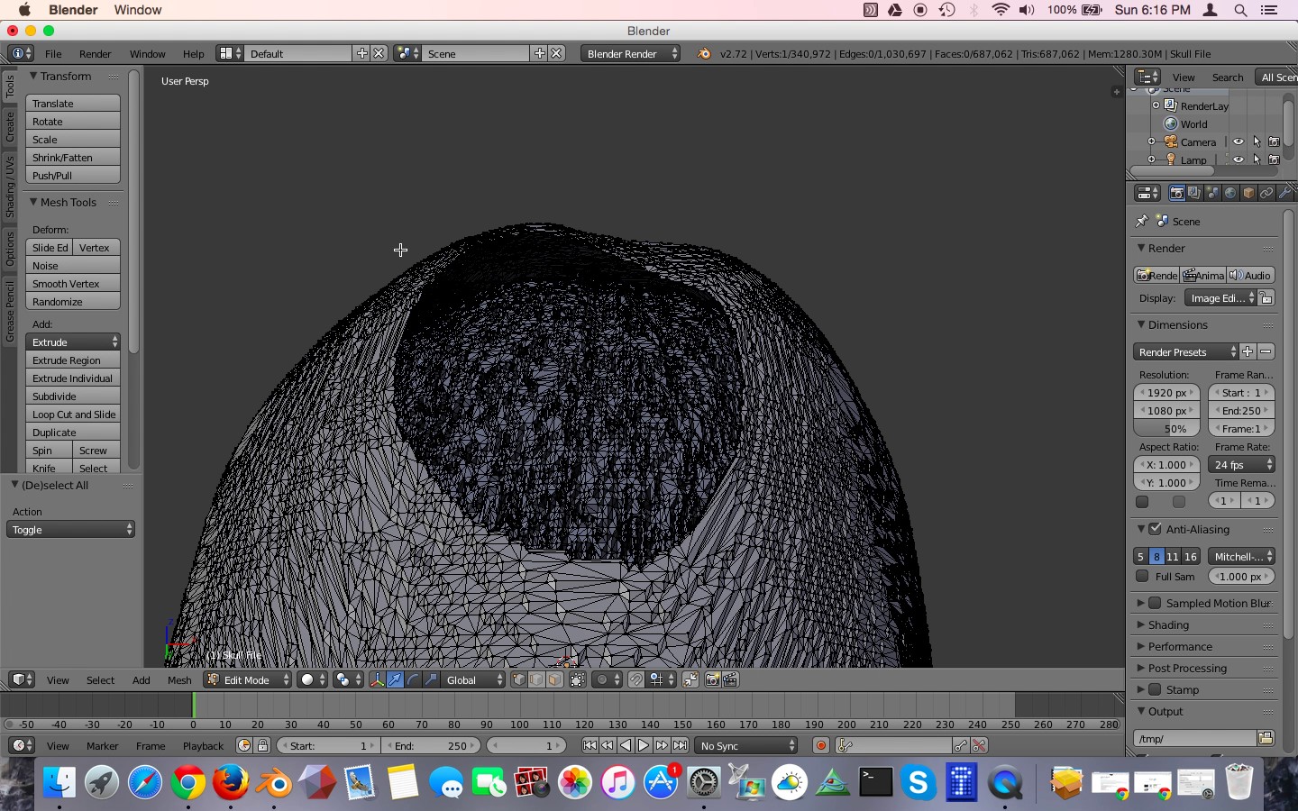
Figure 27: A large open mesh hole at the top of the skull.
Using the Select menu in the lower left-hand corner, click on Non-Manifold. This will select all of the non-manifold mesh defects in your model. You can see that the edge of our large hole at the top of the skull has been selected and turned orange. This confirms that this defect has to be fixed.
Unselect by hitting the A key. Then, go to Edge select mode by clicking on the Edge Select button along the lower toolbar. Holding down the Alt key, right-click on one of the edges of the target defect, in this case the top of the skull. That familiar orange ring has formed. Your selection should look like Figure 28. Let's fill in this hole by creating a new face. Hit the F key. This creates a new face to close this hole, Figure 29.
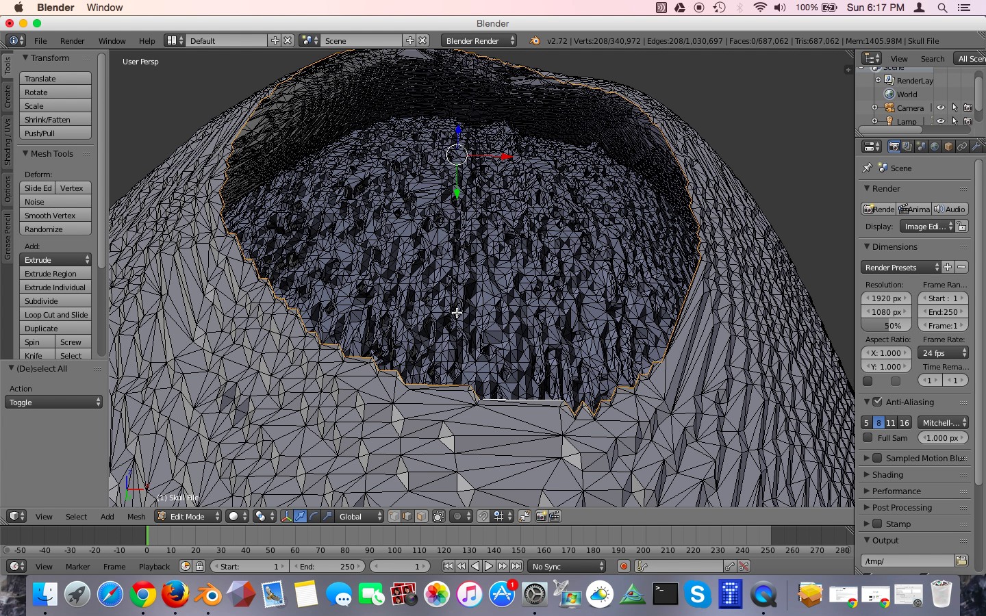
Figure 28: The edge of the hole is selected, as indicated by the orange color.
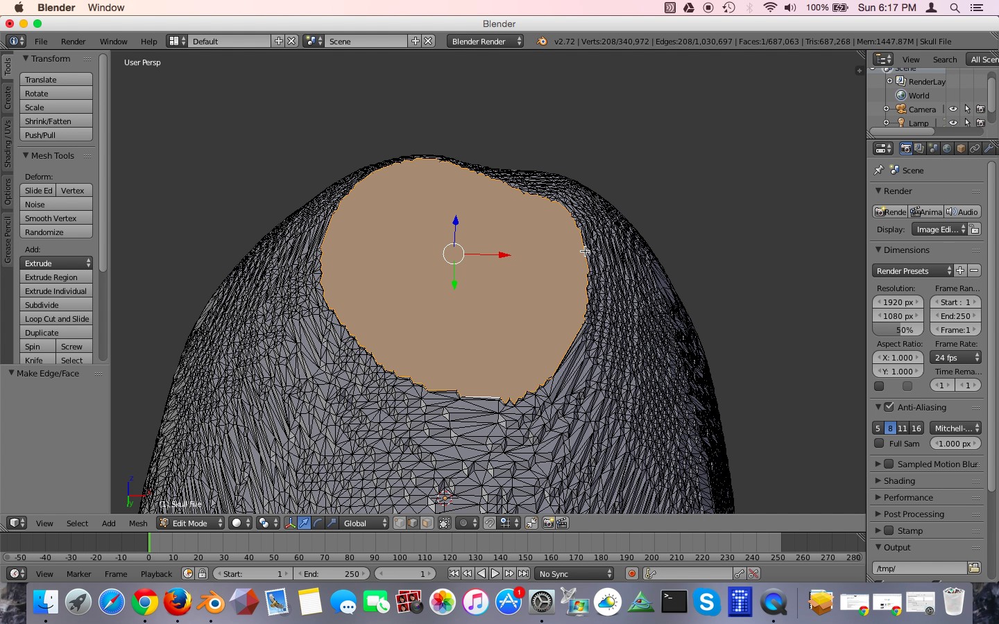
Figure 29: The hole when filled with a new face.
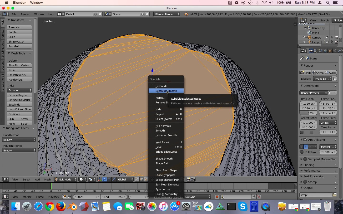
Due to the innumerable polygons along the edges, the face is actually quite a complex polygon itself. Let's convert it to a simpler geometry. With the face still selected hit Control T. You can alternatively go to the Mesh menu and select Faces, Triangulate Faces as shown in Figure 30. This will convert the complicated face into simpler triangles. As you can see, some of these triangles are quite large relative to the other triangles along the skull surface. These large triangles may become apparent when smoothing algorithms are applied or 3D printing is performed. Let's reduce their size. Hit the W key and then select Subdivide Smooth, as shown in Figure 31. The triangles are now subdivided. Let's repeat that operation again so that they are even smaller. Hit the W key and again select Subdivide Smooth.
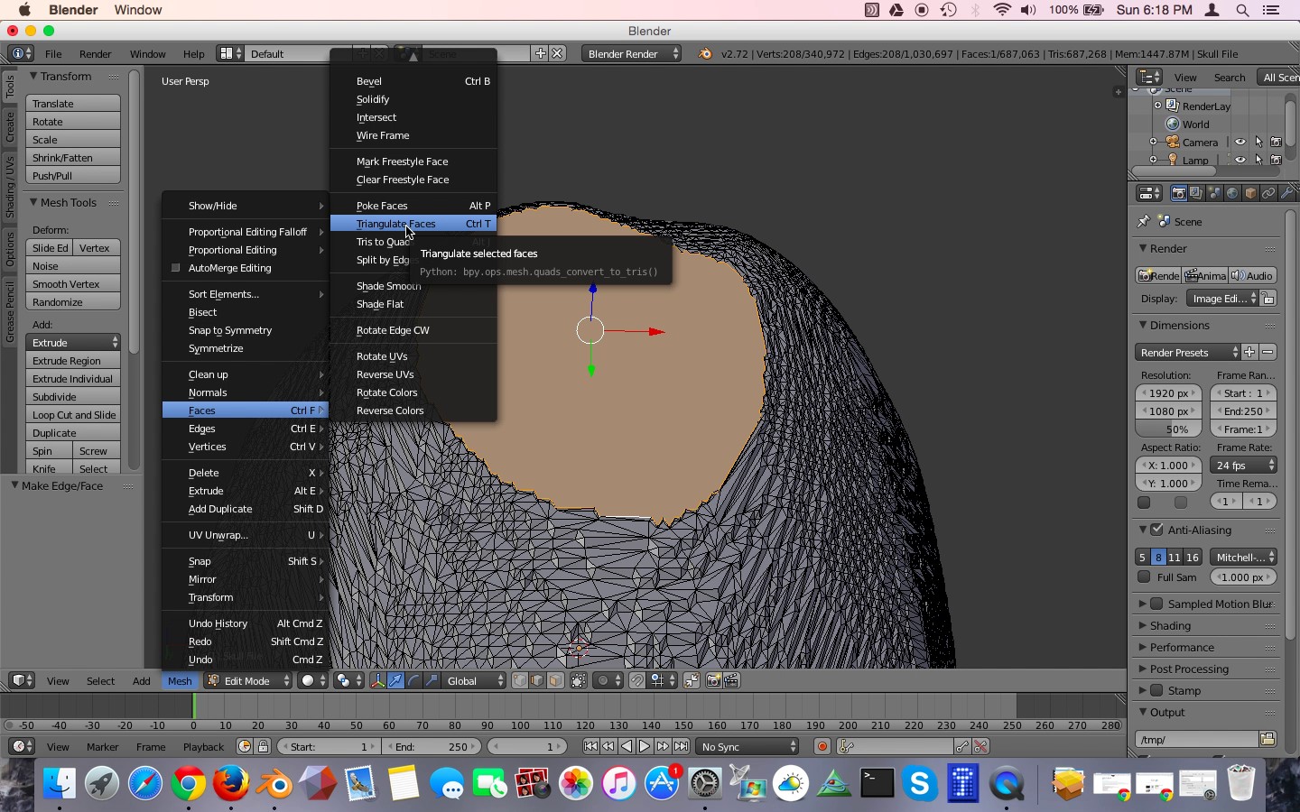
Figure 30: Converting all faces into triangles.
]
Figure 31: Subdividing and smoothing the selected faces.
Smoothing the Model Surface
Next let's get rid of that pixelated appearance of the model surface. First, we need to convert all of the polygons in the model to triangles. The smoothing algorithms just work better with triangles. Staying in Edit mode, hit the A key. The A key toggles between selecting all and unselecting all. If you need to, hit the A key a second time until the entire model is orange, thus indicating that it is selected. Hit Control-T, or alternatively use the Mesh menu, Faces, Trangulate Faces. This will convert any remaining complex polygons to triangles.
Go back to Object mode by hitting the tab button or selecting Object Mode from the bottom toolbar. We are now going to apply a smoothing function, called a modifier, to the skull. Along the right of the screen you'll see a series of icons, one of which is a wrench, as shown in Figure 32. Click on that. This brings up the modifier panel, a series of tools that Blender uses to manipulate digital objects. Click on the Add Modifier button and select the Smooth modifier. Do not select the Laplacian Smooth modifier. That is different. We just want the regular Smooth modifier, as shown in Figure 33. Leaving the Factor value at 0.5, increase the Repeat factor until you are satisfied with the surface appearance of your model. For me, a factor of 20 seemed to work, Figure 34. At this point the modifier is only temporary, and has not been applied to the model. Click on the Apply button. Now the smoothing function has been applied to the model.
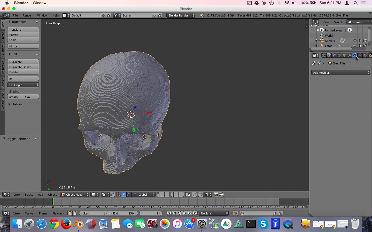
Figure 32: The Modifiers toolbar on the right.
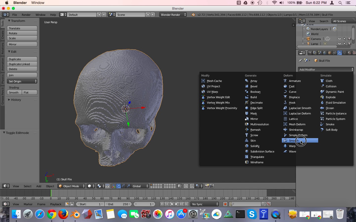
Figure 33: The Smooth modifier
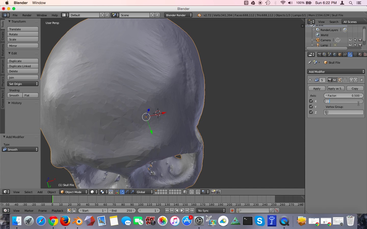
Figure 34: Setting the Smooth modifier to repeat 20 times.
Rotating and Adjusting the Model Orientation
When the model was originally exported from Osirix and opened in Blender, it was at a strange orientation. We can correct to this easily. Click on the View menu from the left portion of the lower now bar and select Front. This orients the model from the frontal view, and you can see that in this orientation we are looking at the top of the skull. To correct this, we will rotate the model along the X axis. First, make sure that the cursor is inside the model window. Then, Hit the R key and then the X key, and type "180." This will rotate the model on the X axis by 180°. Hit the return key to confirm the modification. Don't worry if the skull isn't facing the correct way right now, we will fix that later.
Now we are ready to export our cleaned up skull model. Go to the File menu, click Export, STL. Navigate to your desired folder and save your STL file. Since I corrected several defects in this mesh file, I called the file "skull file corrected.stl"
Performing a Final Inspection Using Meshmixer
If you haven't already done so, go to the Autodesk Meshmixer website at http://www.meshmixer.com/download.html and download and install Meshmixer. The software is free. Once installed open the program and select Import. Navigate to your STL file and double-click it. Meshmixer has a variety of nice features, and one of them is a mesh correction function. Once your file is open click on the Analysis button along the left nav bar. Click on Inspector as shown in Figure 35. Meshmixer will now analyze the STL file for obvious mesh defects. Anything that is detected will be highlighted by red, pink, or blue lines. You can see that our skull model appears to be defect free. Click on the done button and quit Meshmixer.
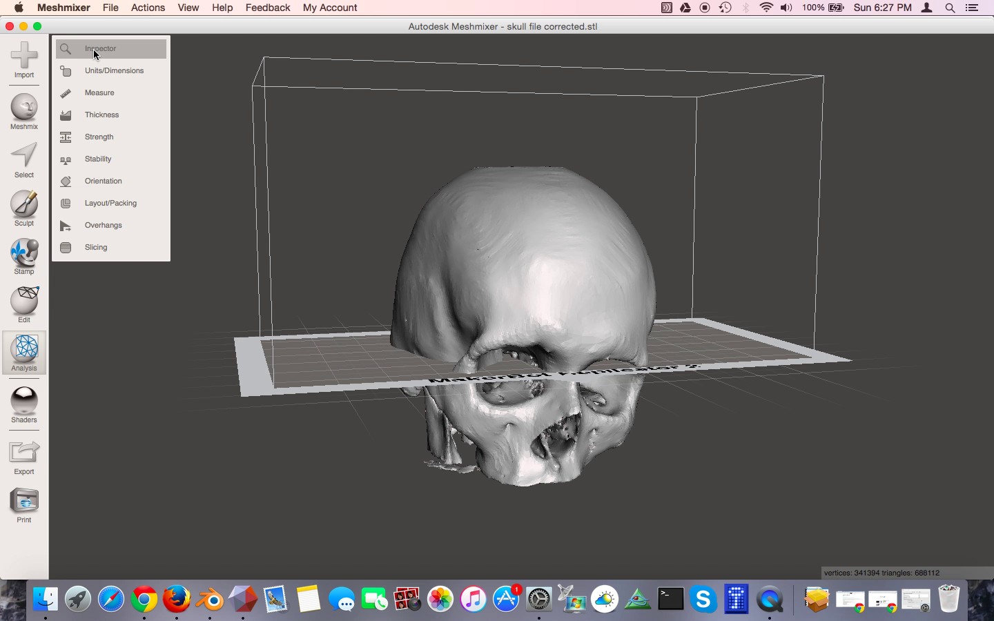
Figure 35: Running the inspector tool in MeshMixer
Your STL file of the skull is now ready for 3D printing!
Conclusion
In this tutorial you have learned how to take a DICOM data set from a CT scan and use it to create a 3D printable STL file using free software. First we used the Osirix to segment a CT scan and convert it to an STL file. Then we performed cleanup operations on the STL file using the Blender and Meshmixer, both free programs. For additional information on how to select an appropriate CT or MRI scan for 3D printing please see my previous tutorial. If you want to learn more about using Blender to fix more extensive defects in bone models, you can view to other tutorials I have created:
- 3D Printing of Bones from CT Scans: A Tutorial on Quickly Correcting Extensive Mesh Errors using Blender and MeshMixer
- Preparing CT Scans for 3D Printing. Cleaning and Repairing STL Files from Bones using Blender, an advanced tutorial
A variety of useful tutorials for 3D printing is available on the Tutorials page. If you are planning on attending the 2015 Radiological Society of North America (RSNA) meeting in Chicago this November, look for my hands-on course "3D Printing and 3D Modeling with Free and Open-Source Software." I will give more tips and tricks for creating great 3D printed medical models using freeware.
I hope you find this tutorial helpful in creating your own medical and anatomic models for 3D printing. Please stay tuned for my next tutorial on using the free, open-source program 3D Slicer to create medical 3D models on Windows and Linux platforms.
If you are creating your own 3D printed medical models, please share your models with the Embodi3D community in the File Vault. If you have questions or comments, please leave a comment below or start a discussion thread in the Forums.
Sample free downloads
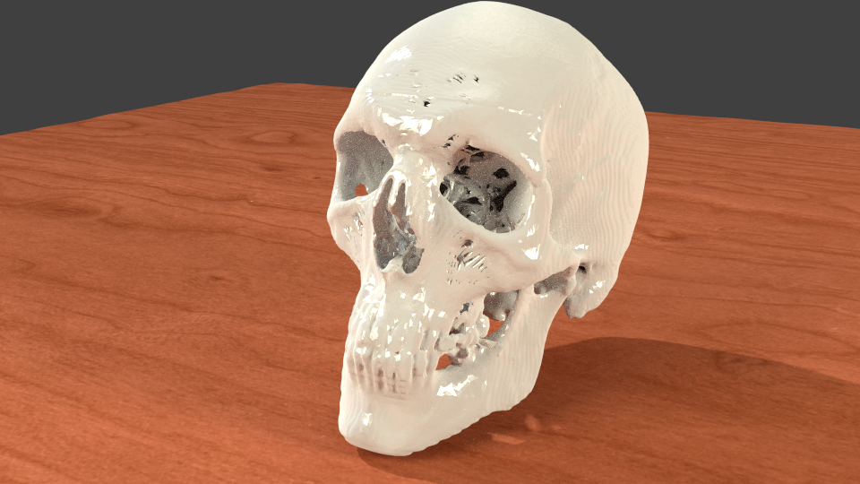
A Collection of Free Downloadable STL Skulls for you to 3D print yourself.
3D printable human heart in stackable slices, shows amazing internal anatomy.
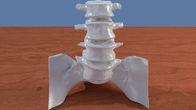
A Collection of Spine STL files to download and 3D print.
Follow Embodi3D on social media


4 Comments
Recommended Comments
Create an account or sign in to comment
You need to be a member in order to leave a comment
Create an account
Sign up for a new account in our community. It's easy!
Register a new accountSign in
Already have an account? Sign in here.
Sign In Now