
Medical 3D Model Creation: From CT Scan to 3D Printable STL File in 20 Minutes Using Free Software Programs 3D Slicer, Blender, and Meshmixer

Entry posted by Dr. Mike ·
81,870 views

Hello, it's Dr. Mike here again with another tutorial on 3D printing. Proprietary software that creates 3D printable models from medical scans typically costs tens of thousands of dollars to license. But, did you know that you can do the same thing using freeware? It's true! In this tutorial I'm going to show you exactly how to do this.
We will be using the free, open-source program 3D Slicer to convert a CT scan of a skull into an STL file ready for 3D model printing. We will also use the freeware software programs Blender and Meshmixer to perform some final cleanup of the STL files before sending them to the printer. All three software programs are available on Windows, Macintosh, and Linux, so you can use the methods described here on almost all personal computers.
If you master this workflow you can create 3D printable models very quickly, as illustrated in my brief tutorial on Creating a 3D Printable Skull in 5 Minutes. If you are on a Mac and prefer to use Osirix, see my tutorial on Creating 3D Printable Models with Osirix. Once you have completed your 3D printable model, be sure to share it with the community via the File Vault, or if you prefer, you can sell it on this website.
Before you began I highly recommend you download the free associated file pack. The file pack contains files that will allow you to follow along with the tutorial, making it easier and faster to learn. This includes the same CT scan used here. The download is free for registered members, and registration is also free and only takes a moment.
Creating a Skull STL File for Medical 3D Printing using 3D Slicer
If you haven't already, download 3D Slicer from slicer.org. Open Slicer.

Drag and drop the folder that contains your DICOM images onto the slicer welcome window, Figure 1. If you downloaded the file pack, the DICOM folder is the one that begins with "1.3.6" followed by a whole bunch of numbers.
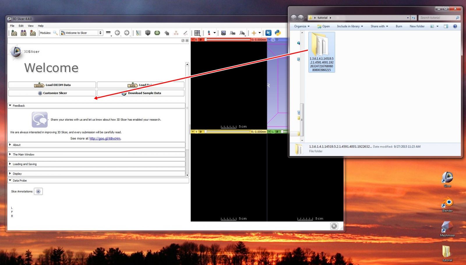
Figure 1: Loading your DICOM data set by dragging and dropping the DICOM folder onto 3D Slicer.
Slicer will ask you to select a reader to use for your data. Leave the default setting selected, "Load directory into DICOM database" and click OK. Slicer will ask you if you want to copy the DICOM files into the Slicer database or just add links to the DICOM files. Click Copy, Figure 2.
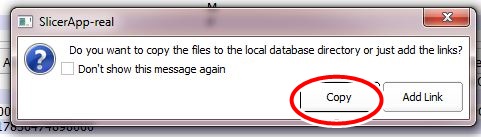
Figure 2: Telling Slicer to copy the DICOM files into the Slicer database.
Slicer will now take a minute or two to load your DICOM data. Once the data has loaded you should get a pop-up box telling you that the study imported successfully. Click OK. At this point a window titled "DICOM Browser" should be showing. Select the study with patient ID TCGA-06-5410. Click on the Load button in the lower left-hand corner, Figure 3.
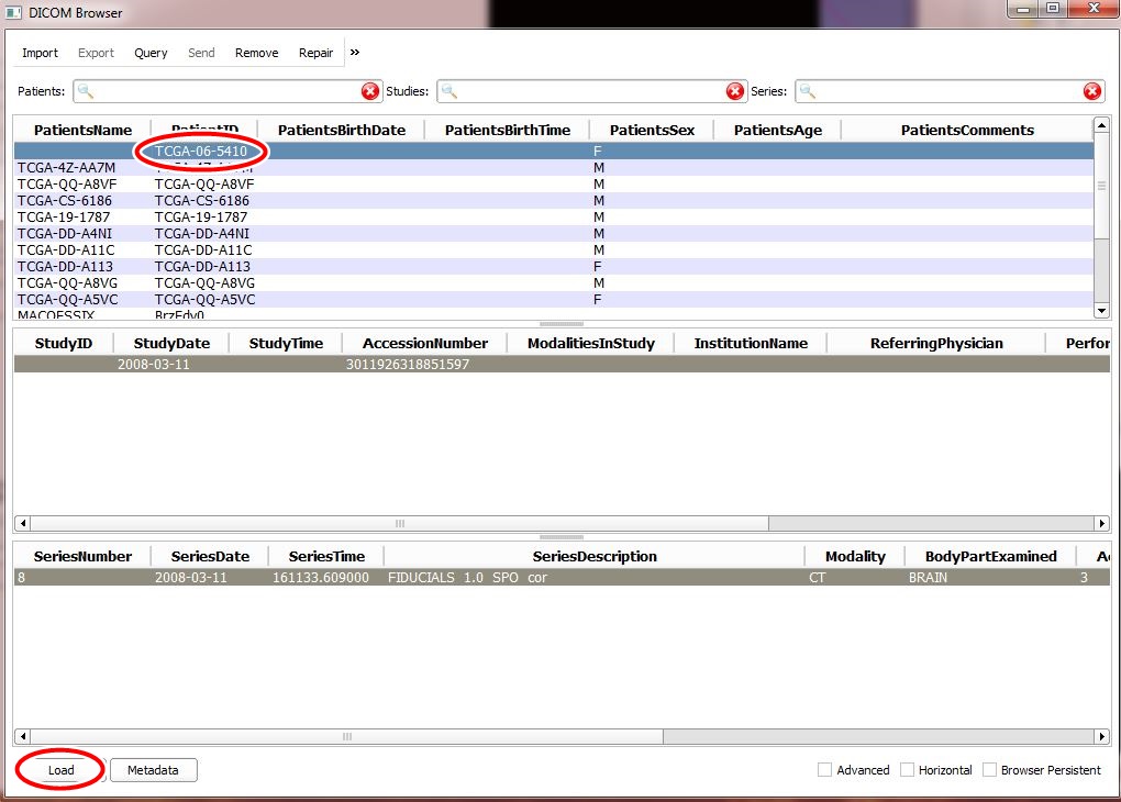
Figure 3: Loading the CT scan into the active seen within Slicer.
At this point you should see a matrix with four boxes in the right half of the Slicer window. In three of the boxes you will see the axial (transverse), sagittal, and coronal views of your imaging study. If you don't see this, you can adjust the viewport layout using the viewport button.

Select the Four-Up viewport layout as shown in Figure 4.
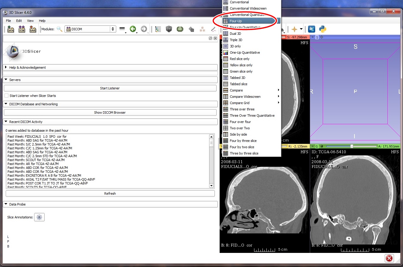
Figure 4: Selecting the Four-up viewport layout.
Next, go to the Volume Rendering module. You can access this from the drop-down menu at the top now bar as shown in Figure 5.
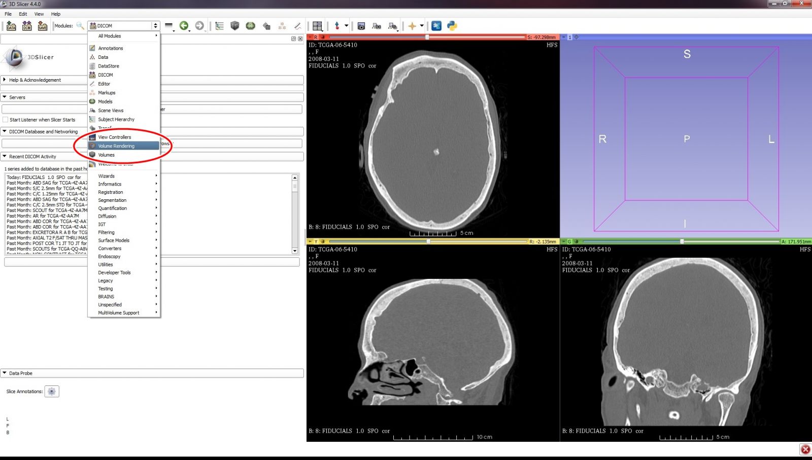
Figure 5: Selecting the Volume Rendering module.
Once you are in Volume Rendering, turn on volume rendering by clicking the small eyeball to the left of the Volume drop-down menu, as shown in Figure 6. The 3D volume should now be displayed in the fourth square on the right part of the Slicer window. However, the volume is likely not centered. To center the volume click on the small crosshairs at the upper left corner of the volume screen, as shown in Figure 6.
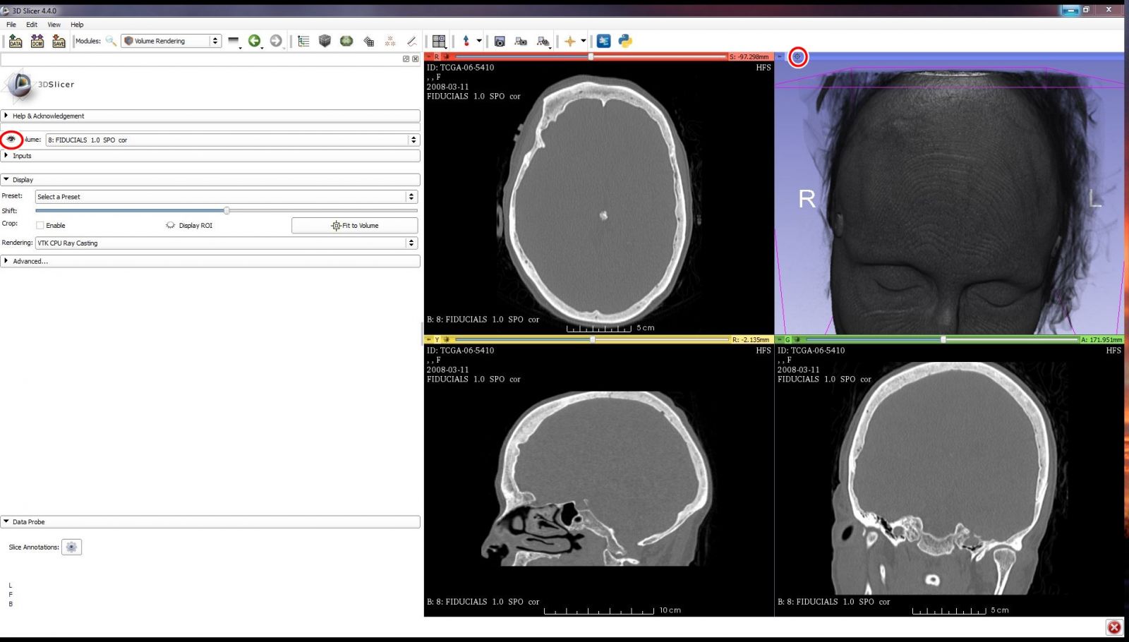
Figure 6: Turning on volume rendering and centering the volume view.
You now need to adjust the appearance of your 3D volume. Under the Display section, select a Preset. For this model, select the third icon from the left on the top row, which should be CT-Bone. Slide the Shift slider to the right until the 3D volume looks good. These actions are shown in Figure 7.
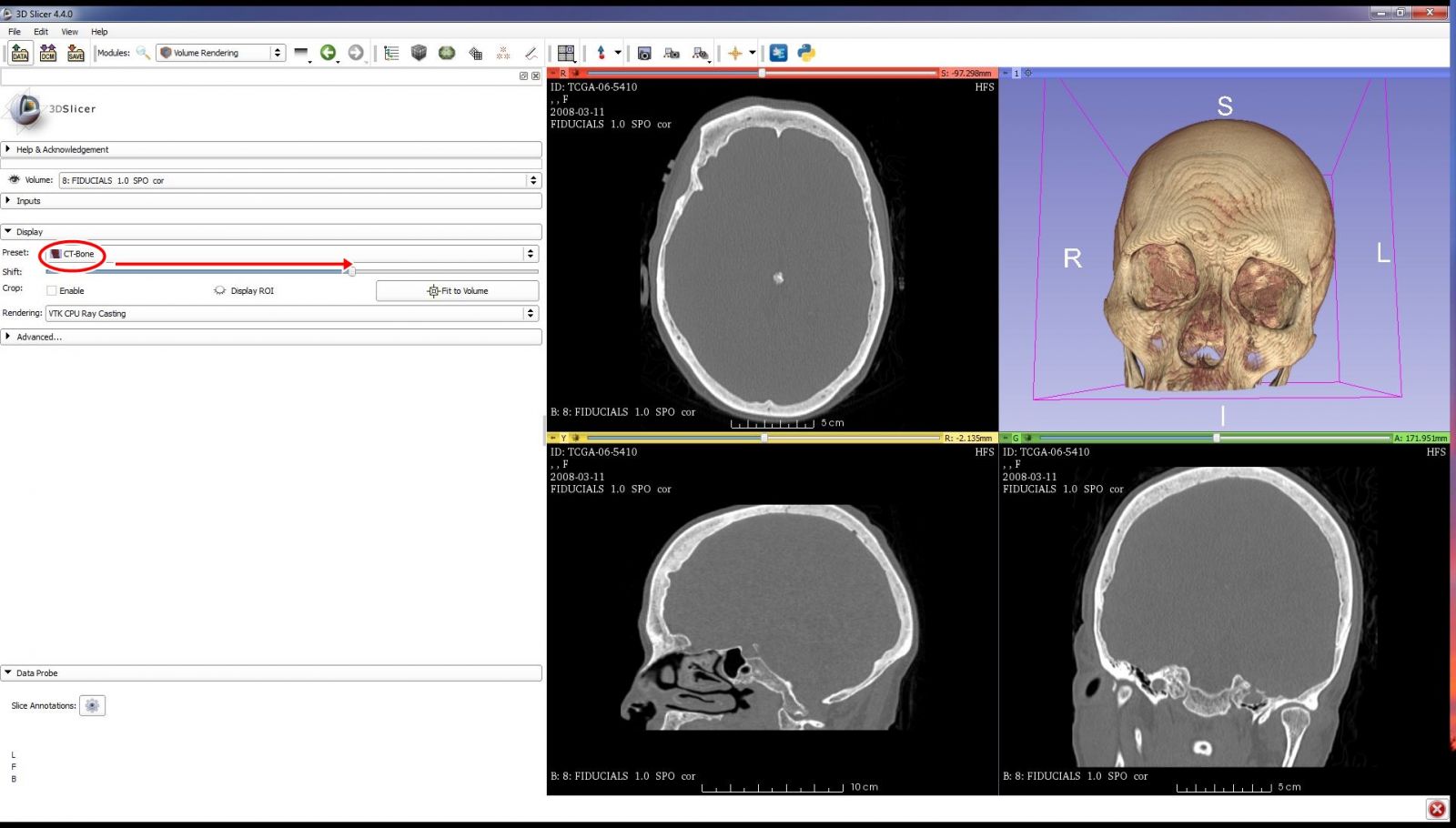
Figure 7: Selecting and adjusting a 3D display Preset.
Now we are going to start actually constructing our 3D surface model. From the module drop-down menu, Editor, as shown in Figure 8. When asked to create a merge label map, use the default selection GenericAnatomyColors, and click Apply, as shown in Figure 9.
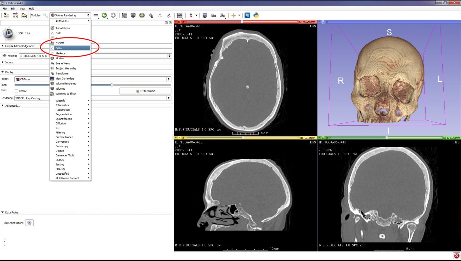
Figure 8: Selecting the Editor module.
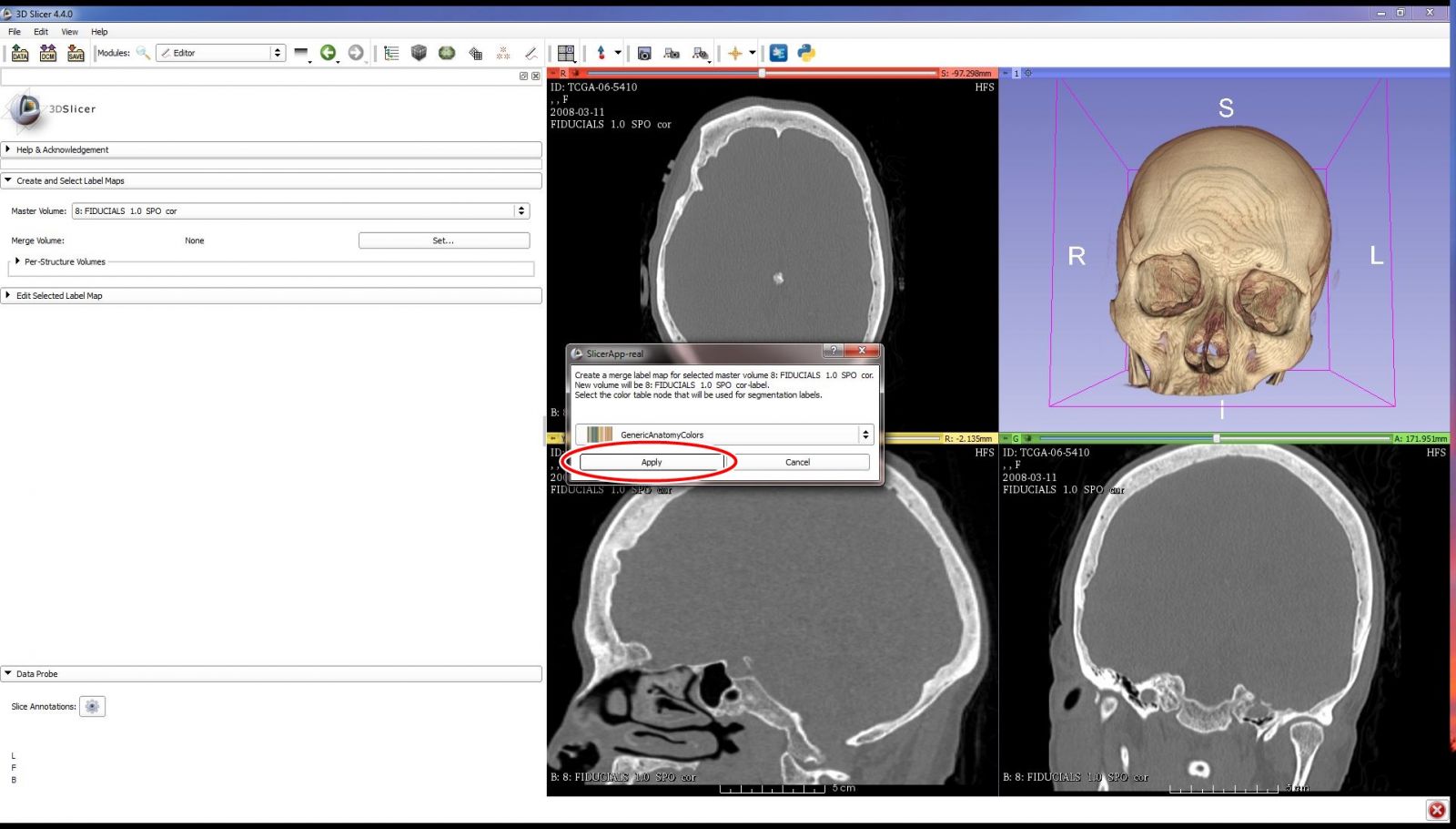
Figure 9: Choose the default merge label map.
First, we're going to create a label map that denotes the skull. Click on the Threshold Effect Tool button. It looks like this.

The threshold effect tool will then open as shown in Figure 10. We want to select bone, so click on the green rectangle to bring up a choice of label maps. Select 2 – bone. The blinking area should turn a yellow-orange color. Next, define the minimum Threshold Range. If you are using the DICOM data set from the file pack, set this to 1250. If you are using your own scan, this will be a different number, probably closer to 300. Experiment with the values until the blinking region seems to encompass the structures you want to 3D print. Leave the default maximum Threshold Range at 4095. The settings that you need to modify are shown in Figure 11. When you are satisfied with your selection, click Apply.
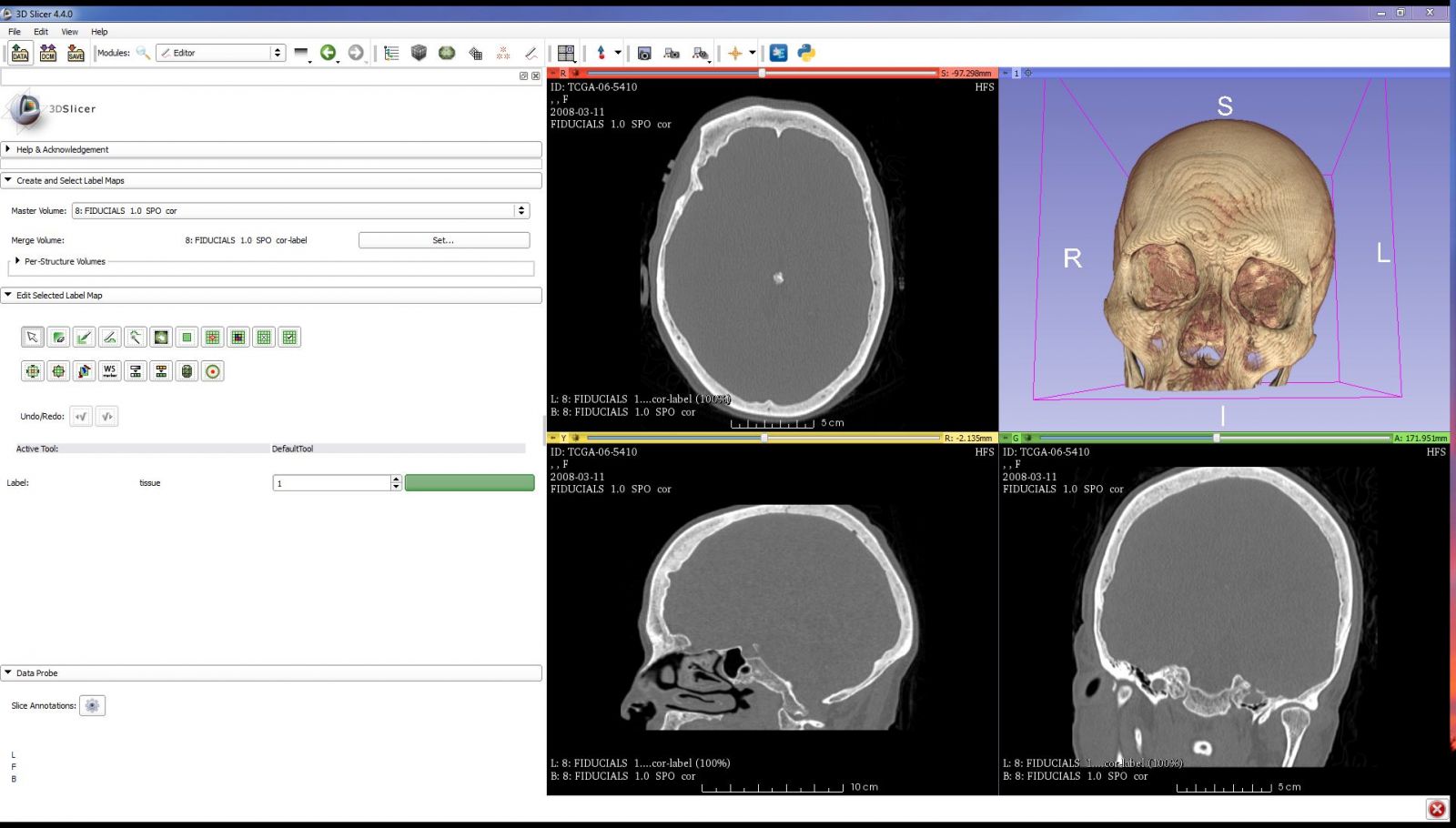
Figure 10: The Threshold Effect Tool.
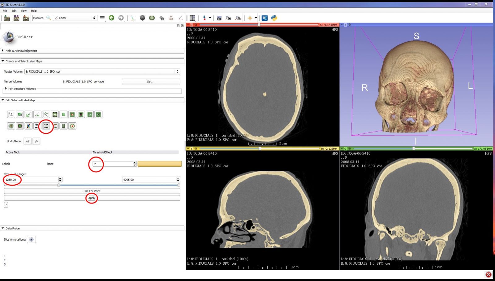
Figure 11: The Threshold Effect parameters to set.
Now you have created a "label map" that encompasses the bony skull we wish to 3D print. We need to generate a surface model. Click on the Make Model Effect button, which looks like this.

Make sure that the target label is still set to 2 (bone). Click Apply, as shown in Figure 12. 3D Slicer will take about 10 seconds to generate the surface model. When it is completed, you will notice a slight change in the appearance of the 3D rendered image in the upper right view box.
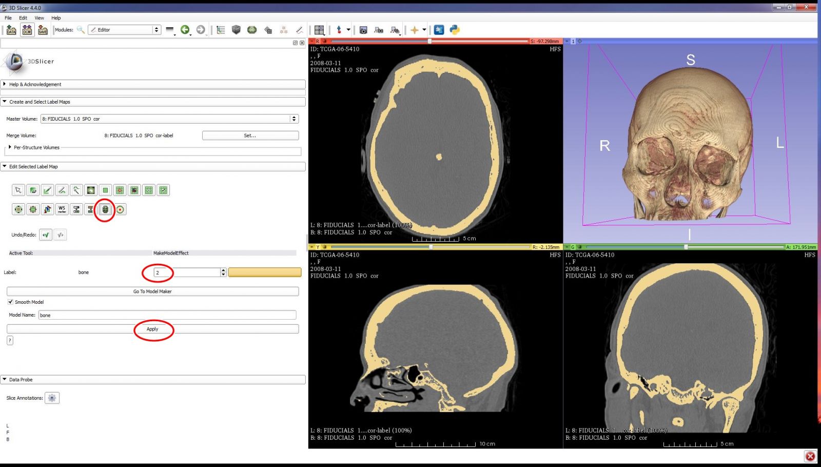
Figure 12: The Make Model Effect tool.
You now have a 3D surface model, and need to save it in STL file format. Click on the save button on the left portion of the upper toolbar. 3D Slicer asks you what you want to save. The only thing we are interested in is the bone surface model, so uncheck everything except "bone.vtk." Choose STL for file format and specify the directory you want the file to be saved, as shown in Figure 13.
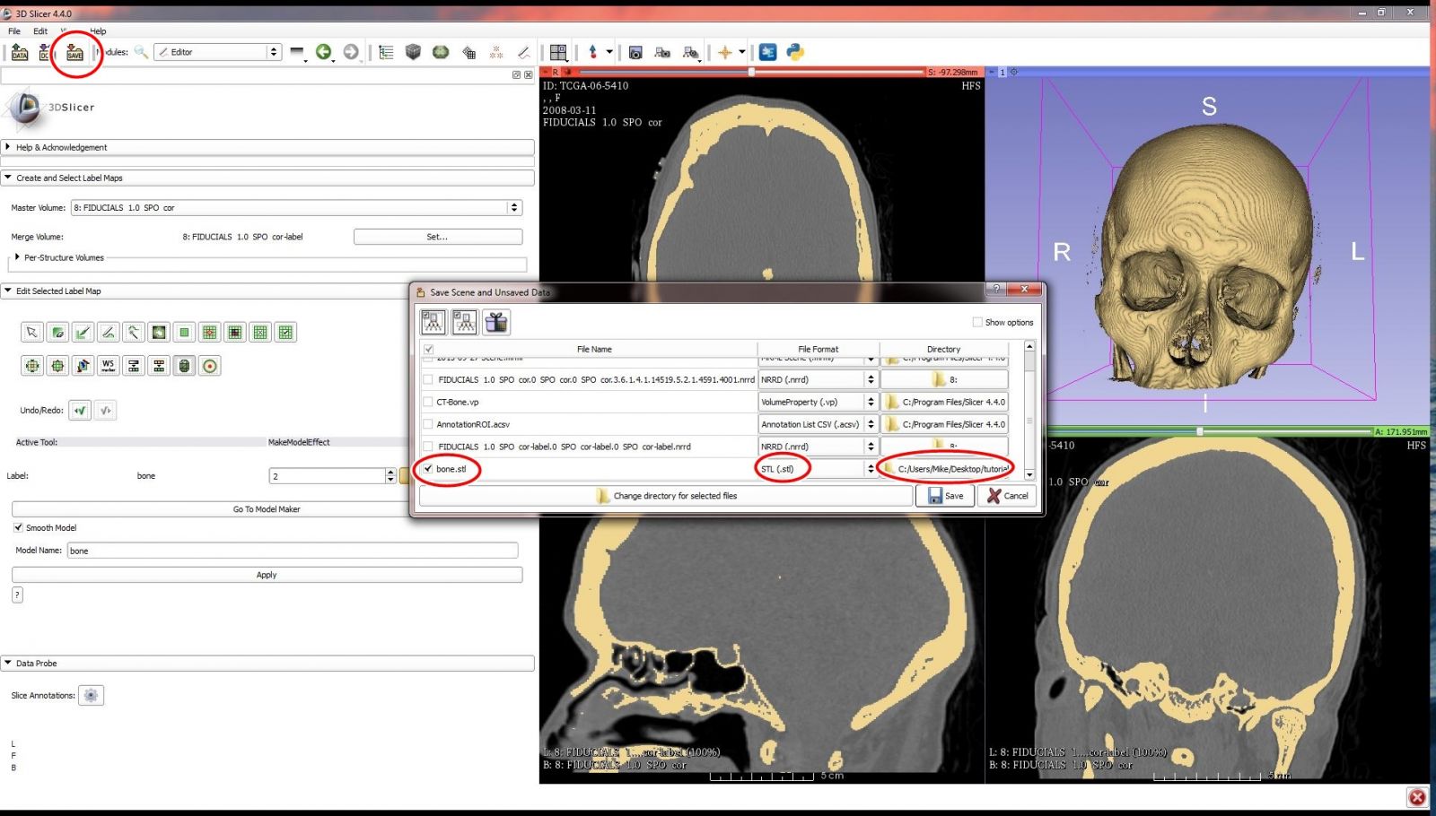
Figure 13: Saving your 3D surface model as an STL file.
You should now have a file called bone.STL. Although tempting to send your new STL file directly to a 3D printer, don't do it. Your file is not yet ready for 3D printing. Fortunately, we can fix most problems with our next software program, Blender.
Performing Additional Skull STL File Cleanup in Blender
If you haven't already, download the free Blender software program from blender.org. Install it and open Blender.

Delete the default cube that is shown in Blender by hitting the X key followed by the D key. Import the STL file by going to the File menu -> Import -> STL, as shown in Figure 14. Blender may take 10 to 15 seconds to import the file as it is fairly large.
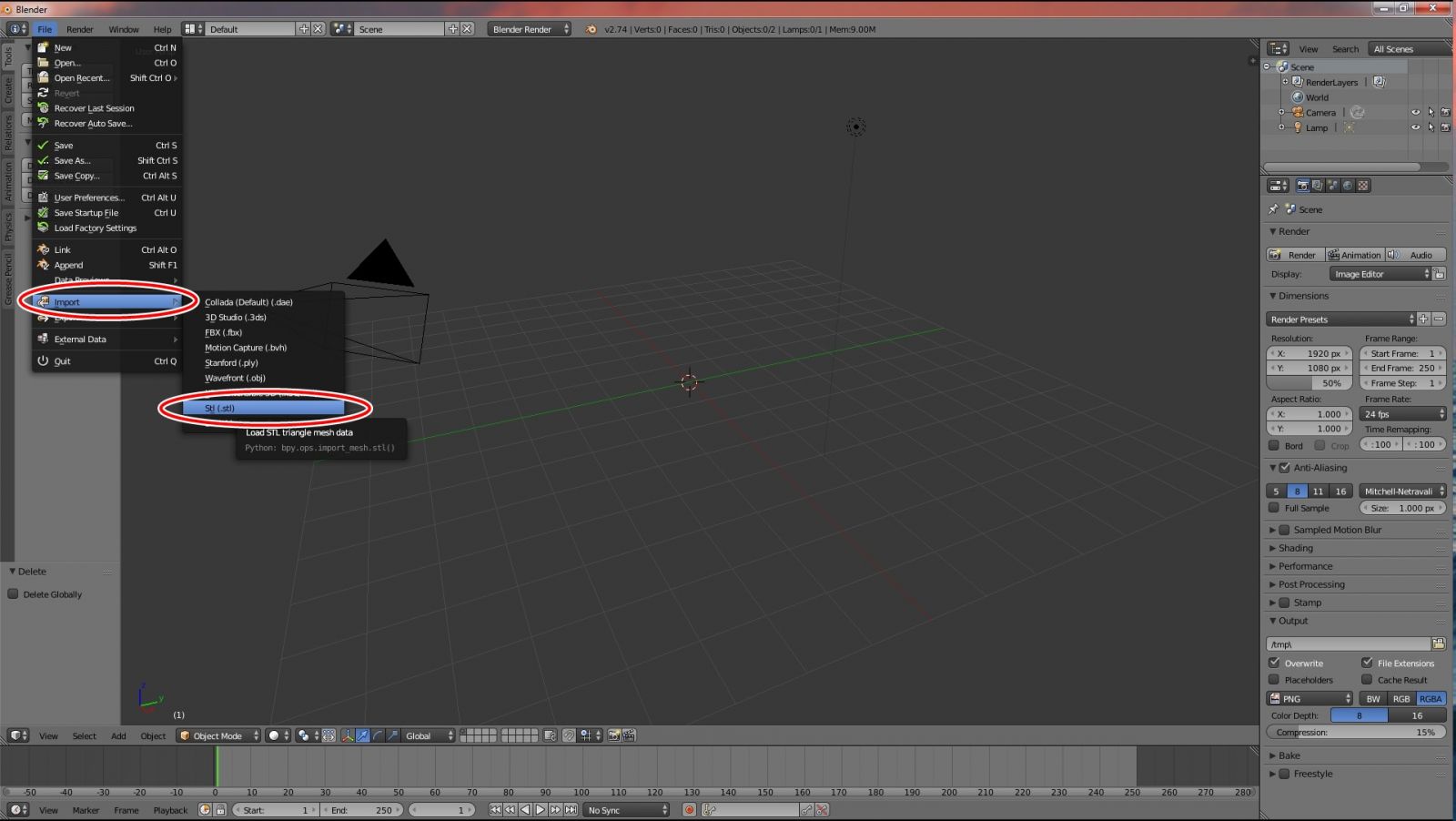
Figure 14: Importing the STL file into Blender.
Next, you need to center the skull object in the field of view. Select the Object menu in the lower left-hand corner, then click Transform -> Geometry to Origin, as shown in Figure 15.
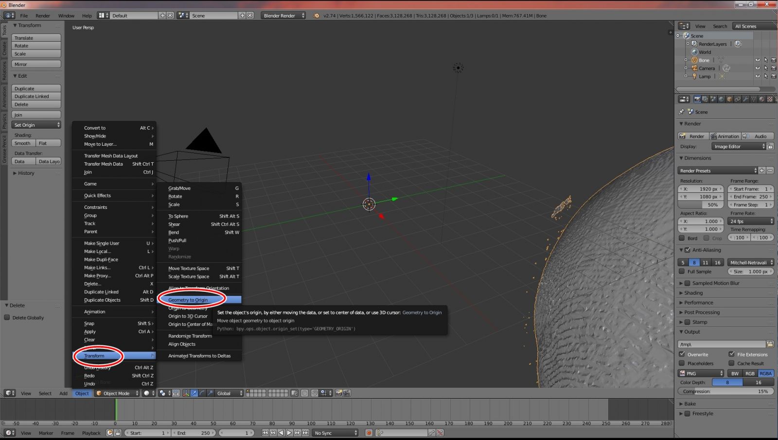
Figure 15: Centering the object in the field of view using the Geometry to Origin function.
You will notice that the imported skull appears quite large. Don't worry about this. Simply use your scroll wheel on the mouse to scroll out. If you have a middle mouse button, you can use it to rotate the skull. Next, we are going to delete the innumerable disconnected mesh islands in our skull object. Go to Edit Mode, as shown in Figure 16.
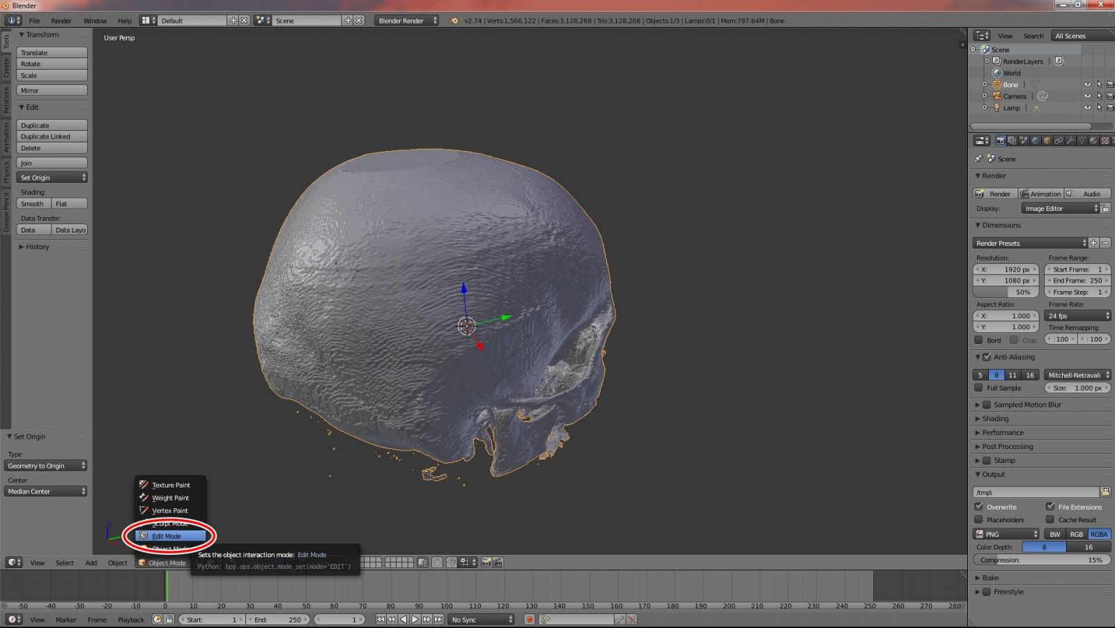
Figure 16: Entering Edit Mode.
When you are in Edit Mode, you can directly edit the mesh of your object. Initially, the entire mesh is selected, thus the skull appears orange. Right click somewhere on the skull. It does not matter where as long as it is not one of the disconnected mesh islands. By right clicking, you will select a single vertex. Expand the selection to include all connected vertices by clicking Control-L on your keyboard. You will notice that the skull has turned orange, but the disconnected mesh islands are still black. Next, we want to invert the selection by hitting Control-I on your keyboard. The selection is now inverted, and only the disconnected mesh islands should be shown highlighted in orange, as shown in Figure 17.
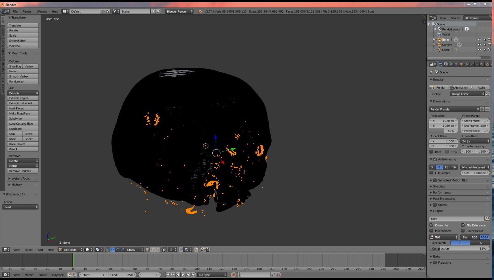
Figure 17: Selecting the disconnected mesh islands.
With the disconnected mesh islands selected, delete them by hitting the X key on the keyboard. A menu of deletion choices is presented. Type "V" for Vertices. This is shown in Figure 18. The disconnected mesh islands are now deleted.
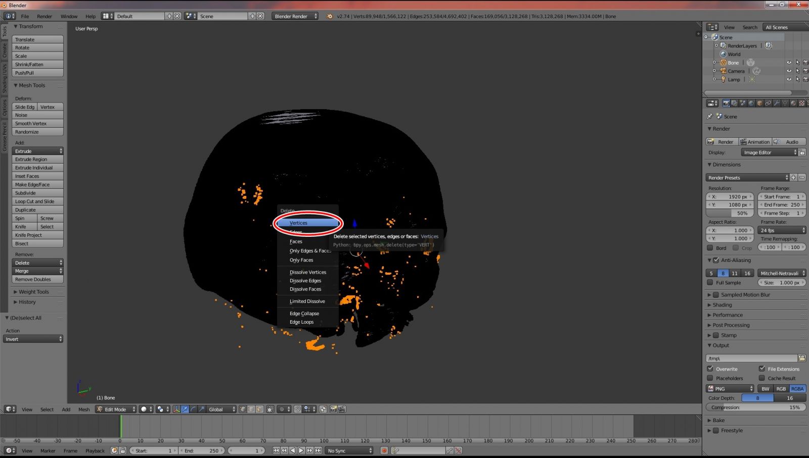
Figure 18: Deleting the vertices of the disconnected mesh islands.
Go back to Object Mode by selecting it from the mode button on the lower left as shown in Figure 19.
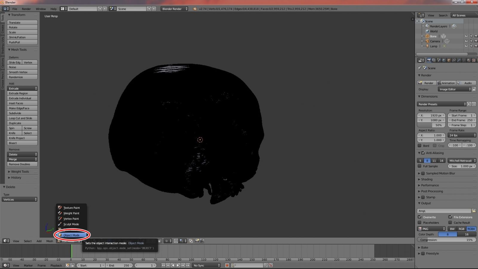
Figure 19: Returning to Object Mode.
From Object Mode select the Modifiers toolbar. It has a button that looks like a small wrench and is located in the right tool column. Modifiers are functions that you can apply to your mesh to change its appearance. In this case, we are going to smooth out our mesh. Click on the Add Modifier menu and select Smooth from the Deform column. DO NOT select Laplacian Smooth. That is a different modifier. The correct selection is shown in Figure 20.
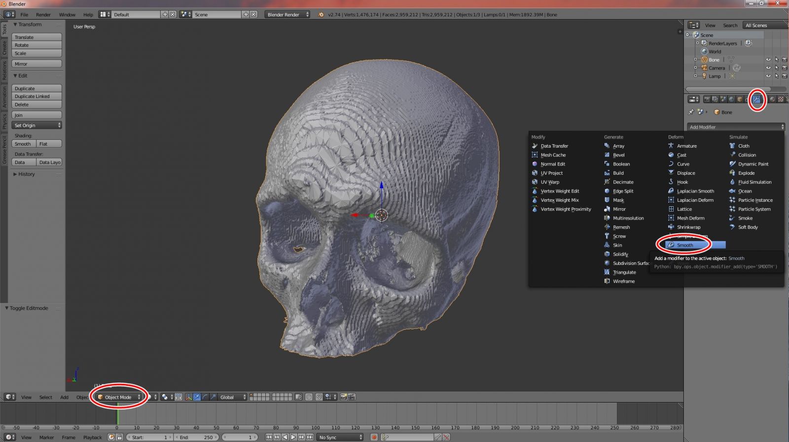
Figure 20: Opening the Smooth Modifier.
Set the Repeat field to 30. Blender may take a few seconds to perform the smoothing function. Then, click Apply, as shown in Figure 21.
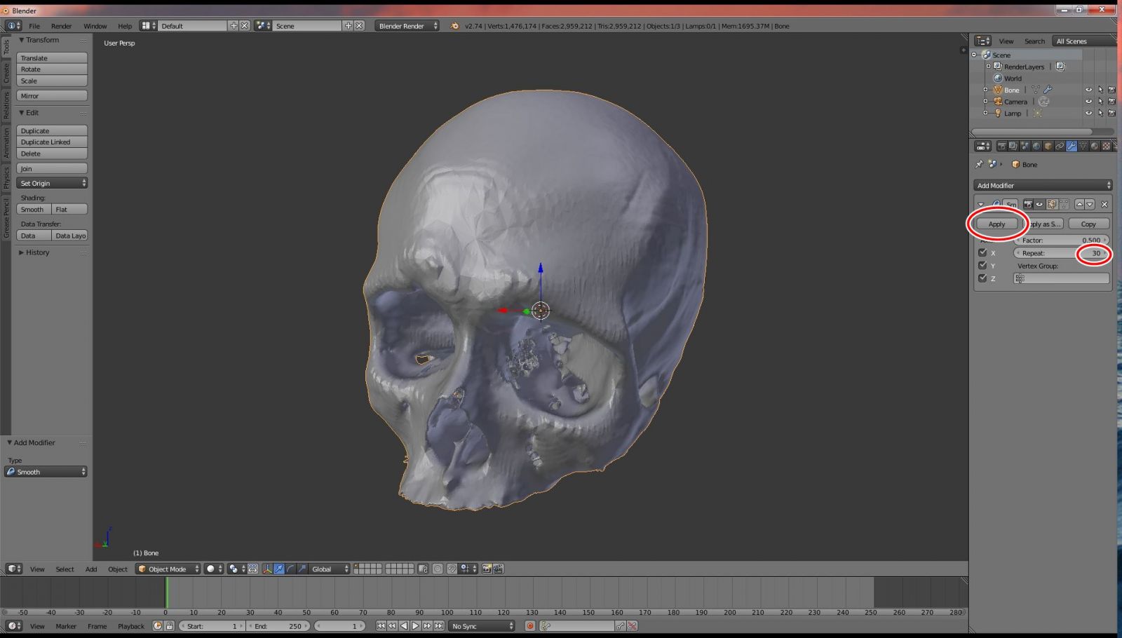
Figure 21: Settings for the Smooth Modifier.
You are now ready to save your smoothed and cleaned-up STL file. From the File menu, select Export -> STL, as shown in Figure 22. Navigate to the folder you want the file to be saved in and type a file name. In this case, we are going to call the file "bone smoothed.stl." Close Blender.
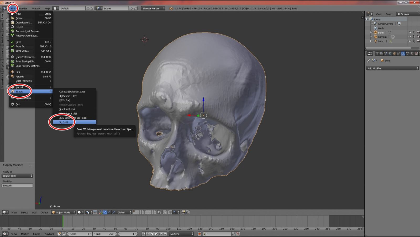
Figure 22: Saving your cleaned-up STL file.
Performing a Final File Check in Meshmixer Before 3D Bioprinting
If you haven't already, download Meshmixer from Meshmixer.com. Open Meshmixer.

Click on the Import button as shown in Figure 23. Select your smoothed STL file that you just created in Blender.
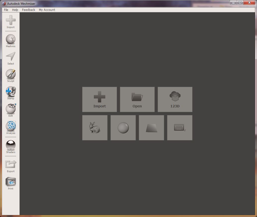
Figure 23: Meshmixer's Import button.
Meshmixer will take 10 to 15 seconds to import the file. Once imported, you can rotate the orientation of your skull object by using the right mouse button. Click on the Analysis button and choose Inspector as shown in Figure 24. The Inspector tool will check your mesh for the defects that could cause problems during 3D printing. Any problem areas will be highlighted by red, blue, or pink lines. In this case, our mesh looks great, without any errors as shown in Figure 25.
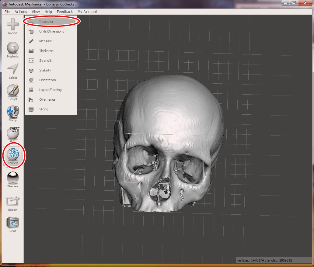
Figure 24: Opening the Inspector tool.
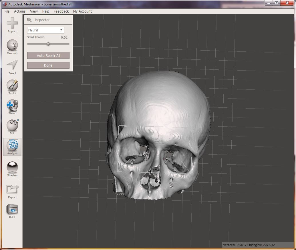
Figure 25: A clean mesh ready to 3D print!
That's it! You have now created a defect-free high quality STL file of the skull from a CT scan using free software. You can take the money you saved by not buying proprietary software to do the same thing, and by yourself a new car or something.
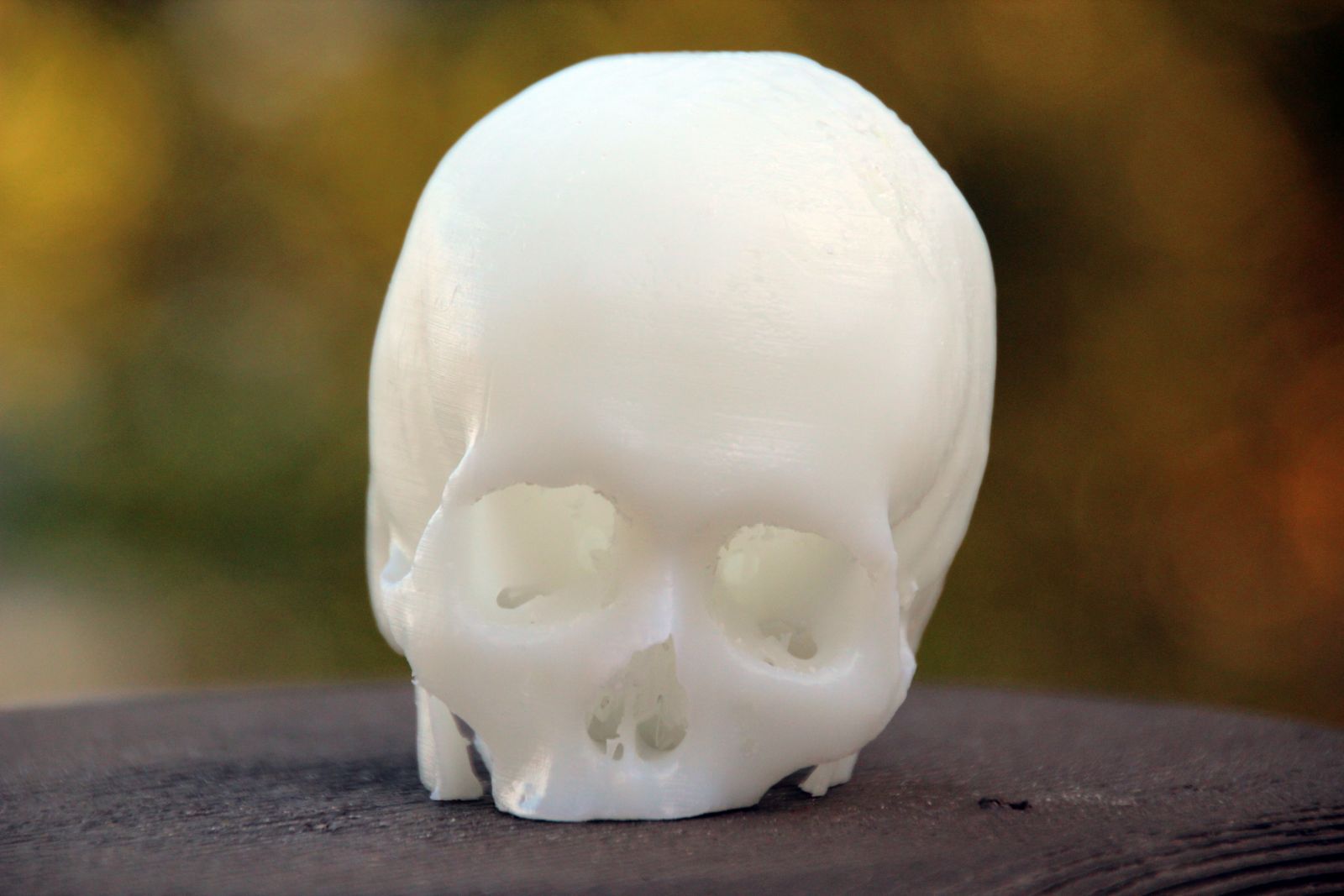
Figure 26: The Final 3D printed product.
I hope you found this tutorial helpful, and you will begin designing 3D printable medical models from medical scans yourself. Embodi3D is here to help you. If you have questions, post them in the comments below or in the Forums. Share 3D printable models you have designed in the File Vault, or download models that others have shared. You can even sell your 3D printable creations! If you want to learn more about how to create 3D printable medical models, there are many more helpful and free tutorials.


10 Comments
Recommended Comments
Create an account or sign in to comment
You need to be a member in order to leave a comment
Create an account
Sign up for a new account in our community. It's easy!
Register a new accountSign in
Already have an account? Sign in here.
Sign In Now