
3D Printing of Bones from CT Scans: A Tutorial on Quickly Correcting Extensive Mesh Errors using Blender and MeshMixer

Entry posted by Dr. Mike ·
30,430 views

Hello and welcome back. Once again, I am Dr. Mike, board-certified radiologist and 3D printing enthusiast. Today I'm going to show you how to correct severe mesh defects in a bone model generated from a CT scan. This will be in preparation for 3D printing. I'll be using the free software programs Blender and Meshmixer.
In my last medical 3d printing video tutorial, I showed you how to remove extraneous mesh within the medullary cavity of a bone. That technique is best used when mesh defects are limited. In instances where mesh defects in a bony model are severe and extensive, a different approach is needed. In this video, I'll show you how to correct extensive mesh errors in bony anatomical models using Blender and Meshmixer. This assumes that you know how to generate a basic STL file from a CT scan. There are a variety of commercial and freeware products that allow you to do this, on a variety of platforms. If you don't yet know how to do this, stay tuned, as I have a series of tutorials planned which will show you how to do this on a variety of operating systems and budgets.
If you wish to follow along with this tutorial, you can download the free tutorial file pack by clicking this link. This is highly recommended, as the files allow you to follow along with the tutorial, which will make learning easier. Included is the STL file used in this tutorial. Also, a powerful Blender script is included which will enable you to easily and efficiently prepare your own bone models for 3D printing. It's a real timesaver. If you haven't registered at Embodi3D.com, registration is free and only takes a moment.
DOWNLOAD THE ACCOMPANYING FILE PACK. CLICK HERE.
You can watch the video tutorial for a quick overview, or read this article for a detailed description.
Initial analysis using Meshmixer
Let's take a look at an STL file of a talus fracture in the ankle. This 3D model is from a real patient who suffered a fracture of the talus. The talus is the bone in the ankle that the tibia, or shinbone, sits on. This STL file is included in the file pack. Let's open this file in Meshmixer (Figure 1). Meshmixer is free software published by Autodesk, a leading maker of engineering software. If you don't have Meshmixer, you can go to Meshmixer.com and download it for free.
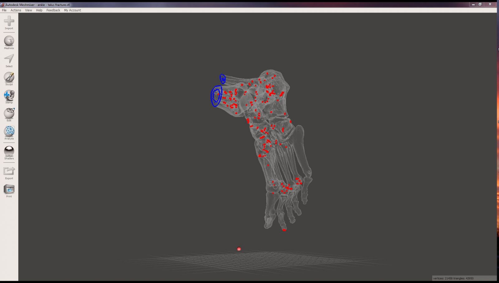
Figure 1
Once you have the file open in Meshmixer, click on the Analysis button and select Inspector. The inspector shows all the errors in this mesh. Blue parts represent holes in the mesh. Red parts show areas where the mesh is non-manifold. Magenta parts show disconnected components. As you can see, there are a lot of problems with this mesh, and it is not suitable for 3D printing in its current state (Figure 2).
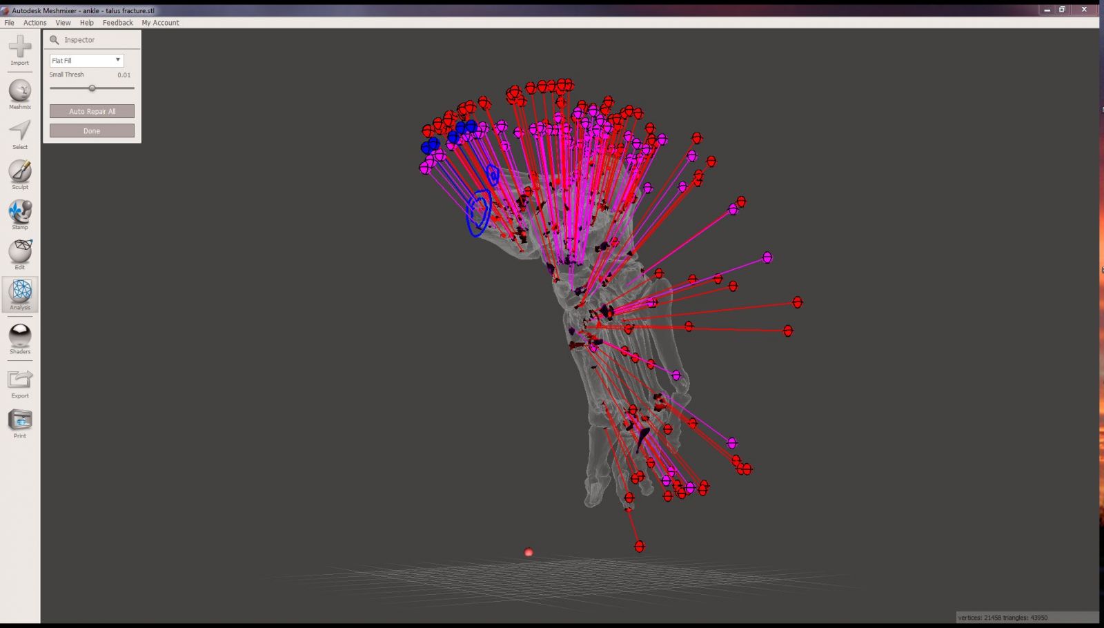
Figure 2
Meshmixer has a feature to automatically repair these mesh defects. However, there are so many problems with this mesh that the auto repair function fails. Click on the Auto Repair All button. Meshmixer has tried to repair these mesh defects, and has successfully reduced the number of defects. However, it is also introduced gaping holes in the model. Entire bones are missing (Figure 3). This clearly isn't the desired outcome.
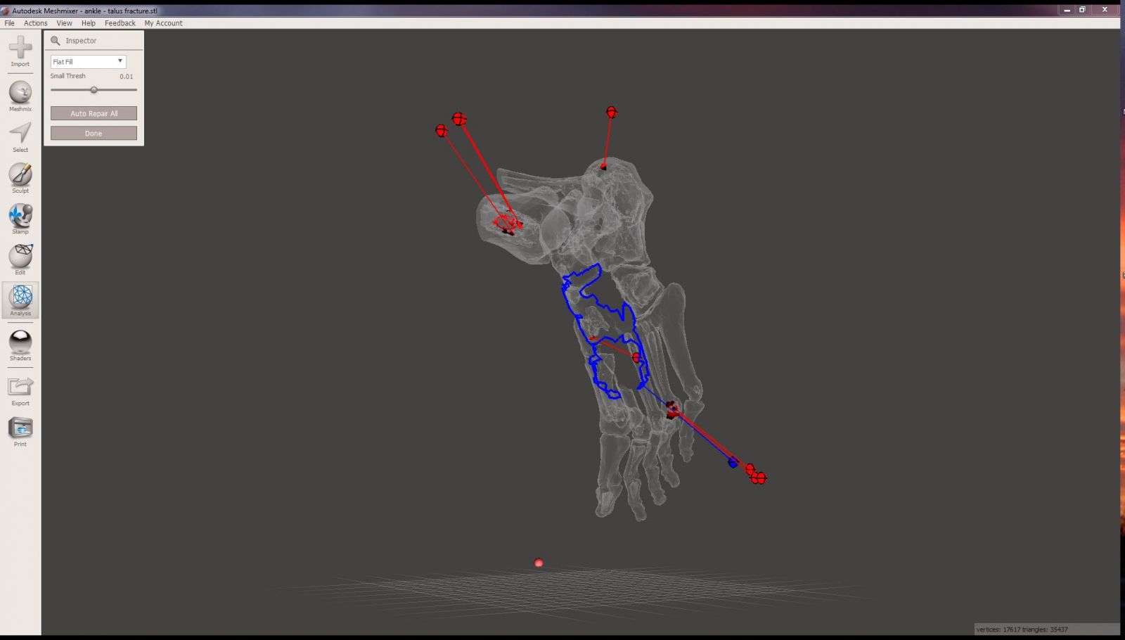
Figure 3
Opening the STL file in Blender
The solution to this problem can be found with Blender. Blender is a free, open-source software package that is primarily designed for animation. It is so feature-rich however, that it can be used for a variety of different purposes, and increasingly is being used for tasks related to 3D printing. If you don't have Blender, you can download it from blender.org. At the time of this writing, the current version is 2.73 a.
Open up Blender. Go ahead and delete the default cube shown in the middle of the screen (Figure 4) by right clicking it and hitting the "X" key followed by the "D" key. If you are new to Blender, you'll soon learn that much of what you can do with Blender can be done with keyboard shortcuts. This can be daunting to learn for beginners, but makes use of Blender very efficient for heavy users.
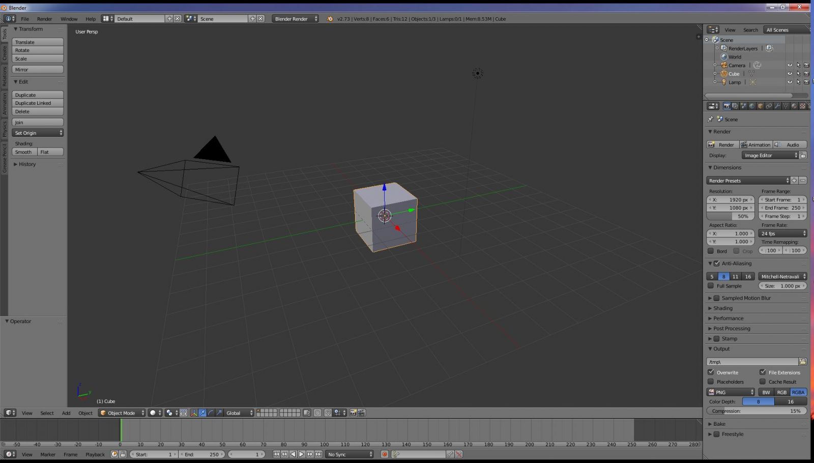
Figure 4
Next open the STL file in Blender. Go to the File menu in the upper left, select Import, and select "Stl (.stl)." Then, navigate to the folder for the tutorial files and select the "ankle - talus fracture.stl" file. You probably don't see anything, as is shown in Figure 5. To understand how this happens, you need to know a little bit about how Blender measures distances. Blender uses an arbitrary measure of distance called a "blender unit." One blender unit is equivalent to one of the little squares seen in the viewport. However, in real life distances are measured in real units, such as feet, inches, centimeters, and millimeters. Most STL files that are generated from medical imaging data have default unit of measurement of millimeters. When Blender imports the file it converts the millimeter units to blender units. Since our imported model is the size of human foot, measuring 240 mm or so, the model will be 240 blender units, or 240 of those little squares, in length. We can't see it because the model is too big! Our viewport is zoomed into much! Zoom out using the mouse wheel way, way back until you can see the model as shown in Figure 6.
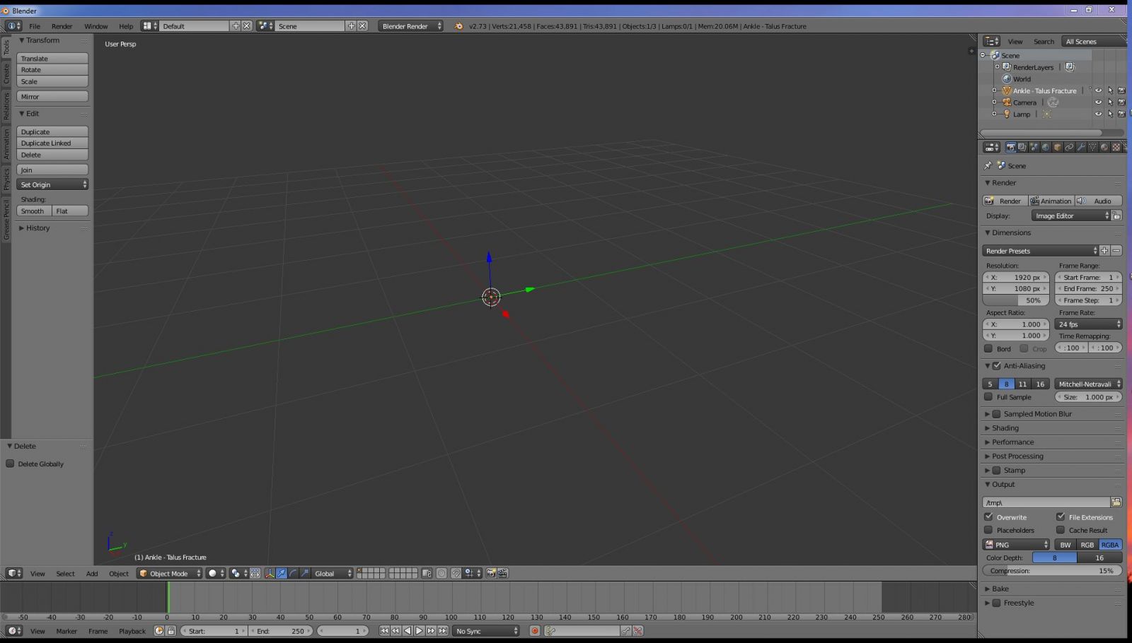
Figure 5: Where is the model?
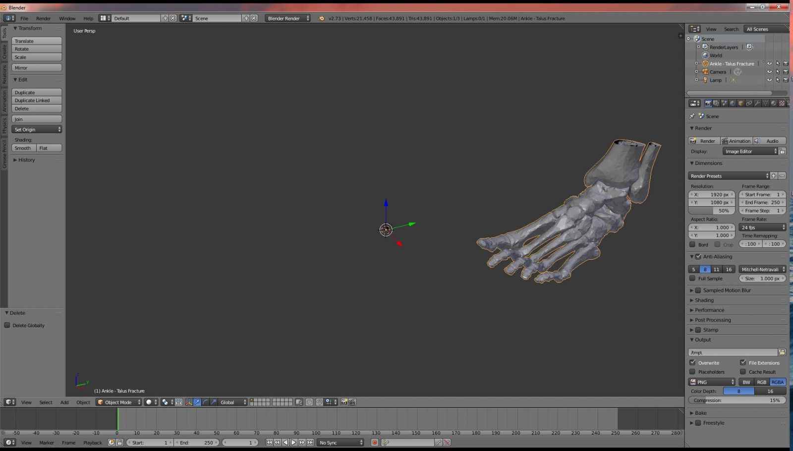
Figure 6: There it is!
Correcting the Object Origin
You will notice that the origin of the ankle object, as shown by the red blue and green axes (Figure 6), is actually outside of object itself. Left uncorrected, this can be a really annoying issue. When you rotate or pan around the object, you will rotate or pan around these three axes, instead of the ankle object itself. Fortunately, correcting this takes only a moment. In the lower left-hand part of the window select the Object menu. Be sure that you have the ankle object selected first. Then choose Transform, Geometry to Origin. The ankle object is then moved to the red blue and green axes. With the object origin now in the center of the mesh, the mesh will be much easier to work with.
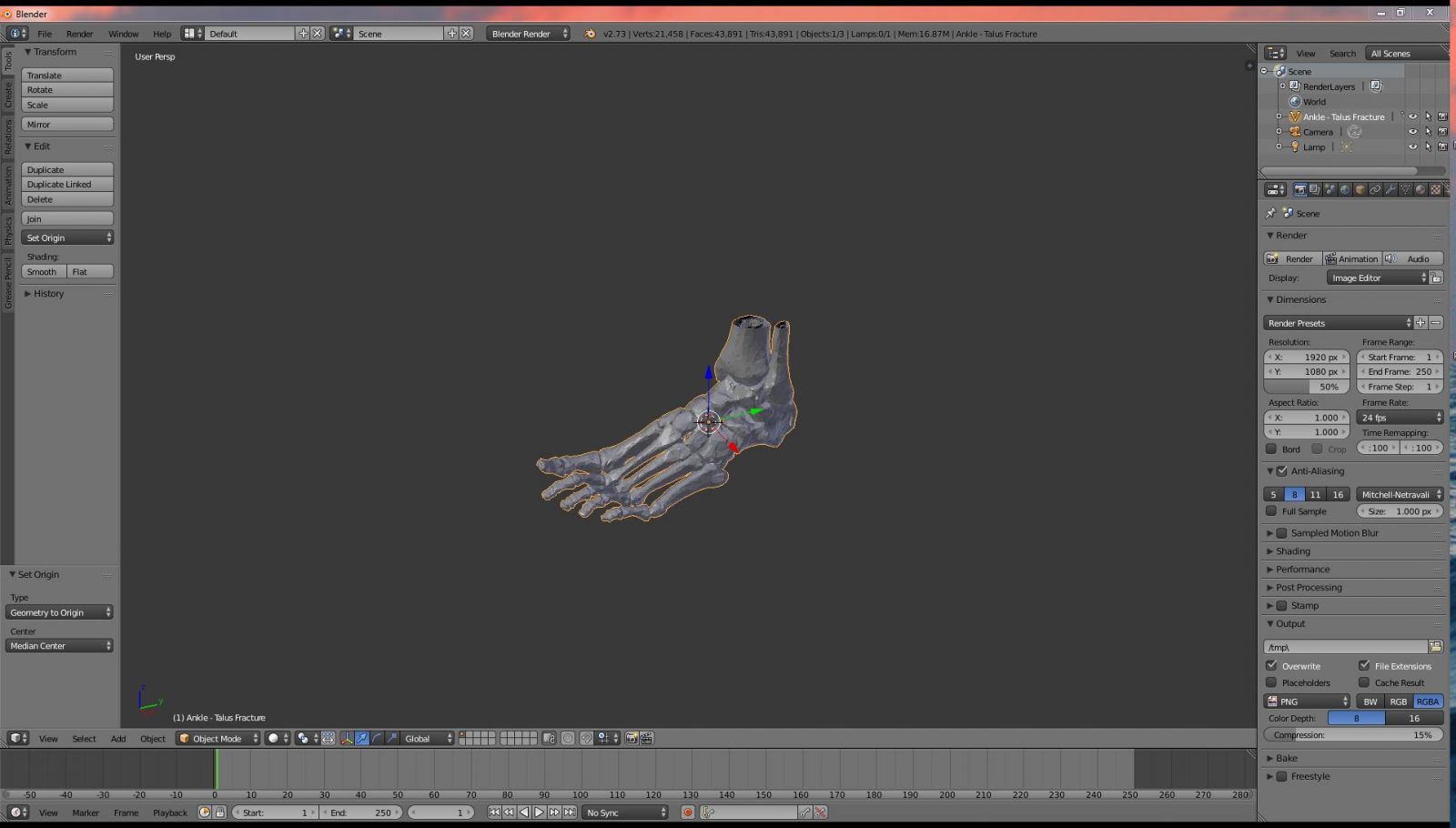
Figure 7: The ankle mesh and object origin are now aligned.
Inspect the ankle mesh
If you look closely at the ankle mesh you can see immediately that it has a lot of problems. In the solid shader mode, the bones look very faceted. The polygons are large, giving the bones a unnatural appearance (Figure 8). Don't worry, will fix this. If you turn on wireframe mode by hitting the "Z" key you can see that there is a lot of extraneous mesh within the bones that represents unwanted mesh from the medullary cavities of these bones (Figure 9). Furthermore, if you check for non-manifold mesh by holding control-shift-alt-M, you'll see that there are innumerable non-manifold mesh defects (Figure 10).
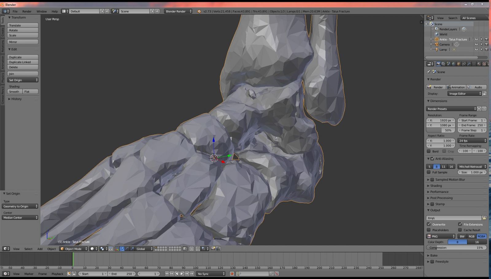
Figure 8: Note the very faceted appearance of the bones.
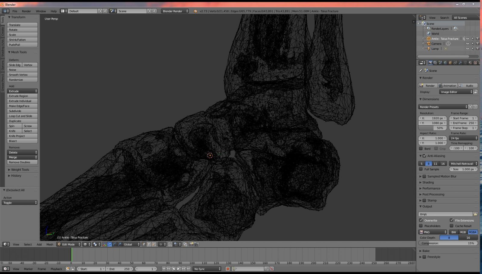
Figure 9: There is a significant amount of unneeded and extraneous mesh, particularly within the medullary cavities of the bones.
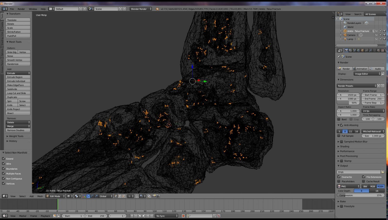
Figure 10: Non-manifold mesh defects.
If you are unfamiliar with the term "non-manifold," let me take a moment to explain. A mesh is simply a surface. It is infinitely thin. If the mesh is continuous and unbroken, and has a contained volume within it, then the mesh can be considered to represent something solid. In this case, the mesh surface represents the interface between the inside of the object and the outside of the object, such as the sphere shown in Figure 11. An object like this is considered to be "manifold," or watertight. It represents a solid that can really exist in the physical world, and can thus be 3D printed.
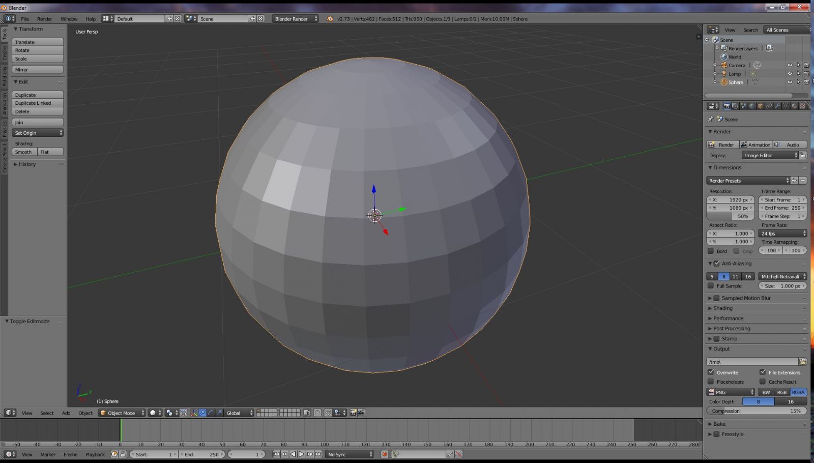
Figure 11
If however, I cut a hole in the sphere, as shown in Figure 12, then there is a gap in the mesh. A 3D printer won't know what to do with this. Is this supposed to be solid like a ball, or hollow like a cup? If it is supposed to be like a cup, how thick are the walls supposed to be? The walls in this mesh are infinitesimally thin, so what is the correct thickness? This mesh is not watertight - that is, should water be placed in the structure it would leak out. The mesh is non-manifold. It cannot be 3D printed. If we use the control-shift-alt-M sequence to highlight non-manifold mesh, as shown in Figure 13, we can see that Blender correctly identifies the edge of the hole as having non-manifold mesh.
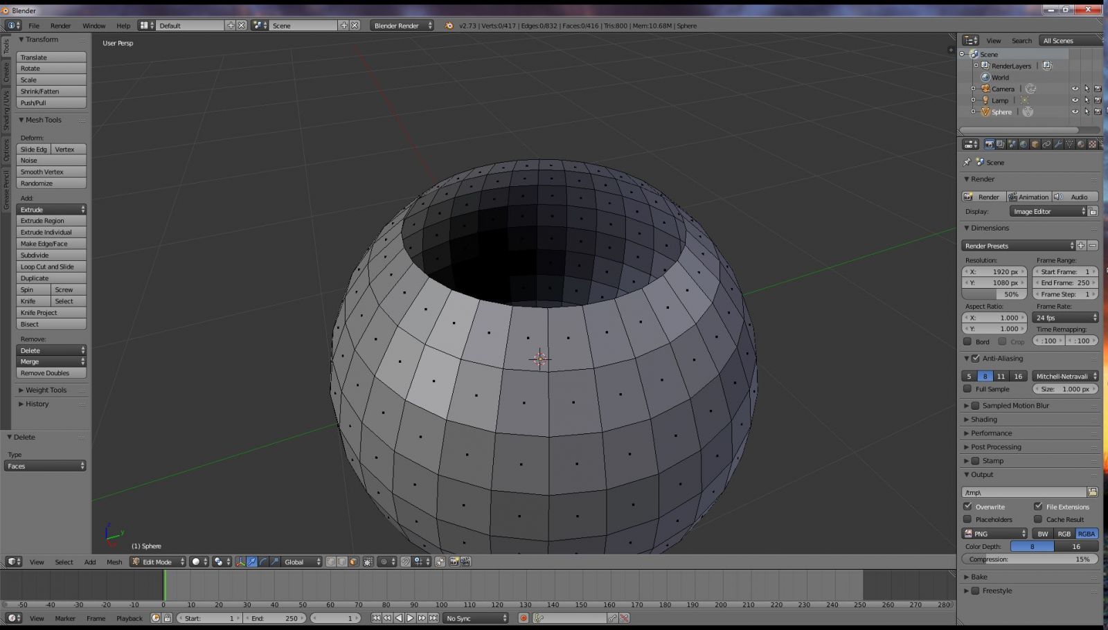
Figure 12

Figure 13
Closing major holes manually in Blender
In this particular mesh, there are many, many small mesh errors and two very large ones. The distal tibia and fibula bones have been cut off by the CT scanner, leaving gaping holes in the mesh as shown in Figure 14. Fixing these manually will only take a moment and make things easier down the road, so let's take care of that now. Enter Edit mode by hitting the Tab key, or clicking it in the Mode menu. If you hit control-shift-alt-M to select non-manifold edges, you can clearly see that these bone cuts are a problem as shown in Figure 15.
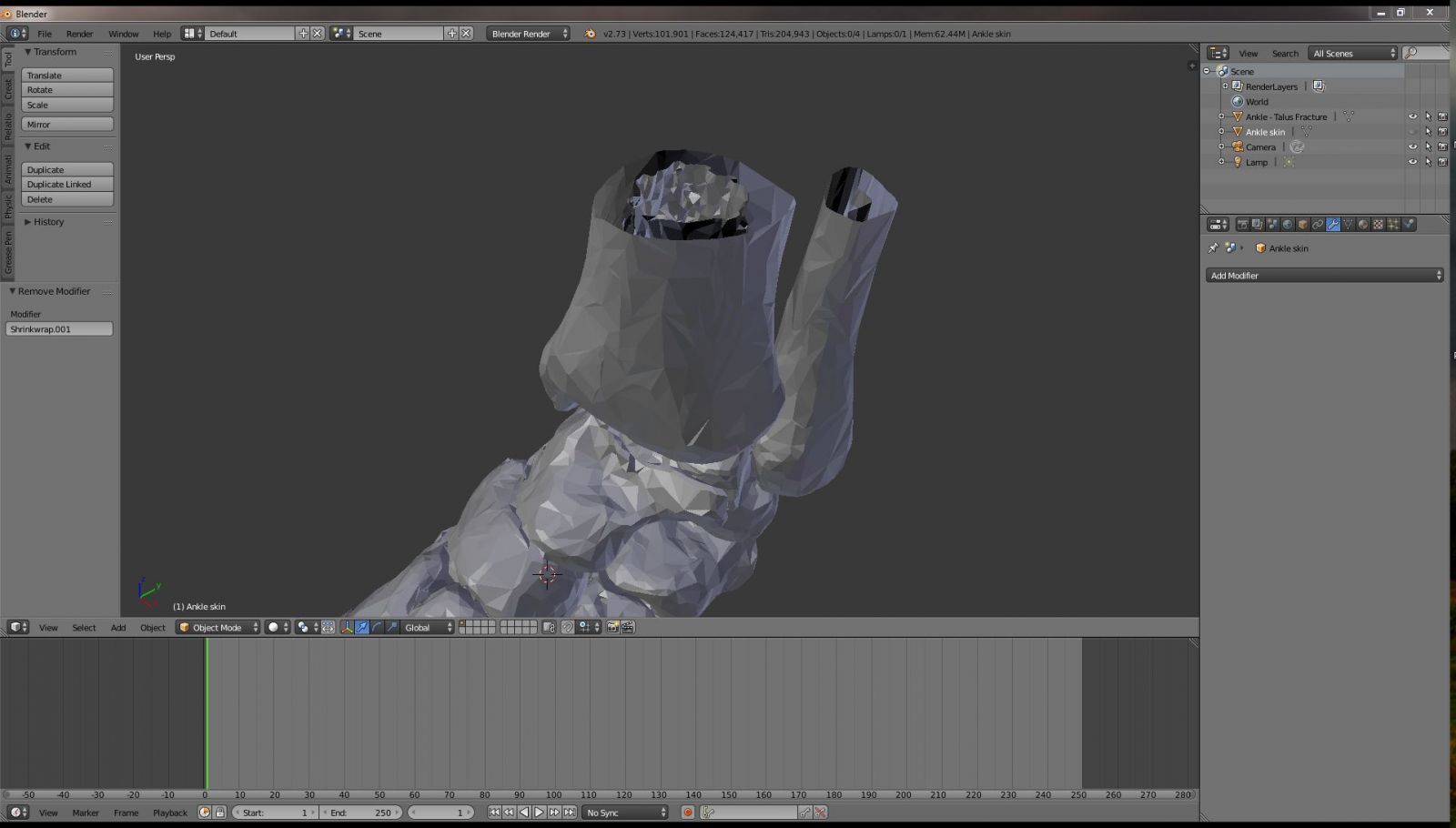
Figure 14
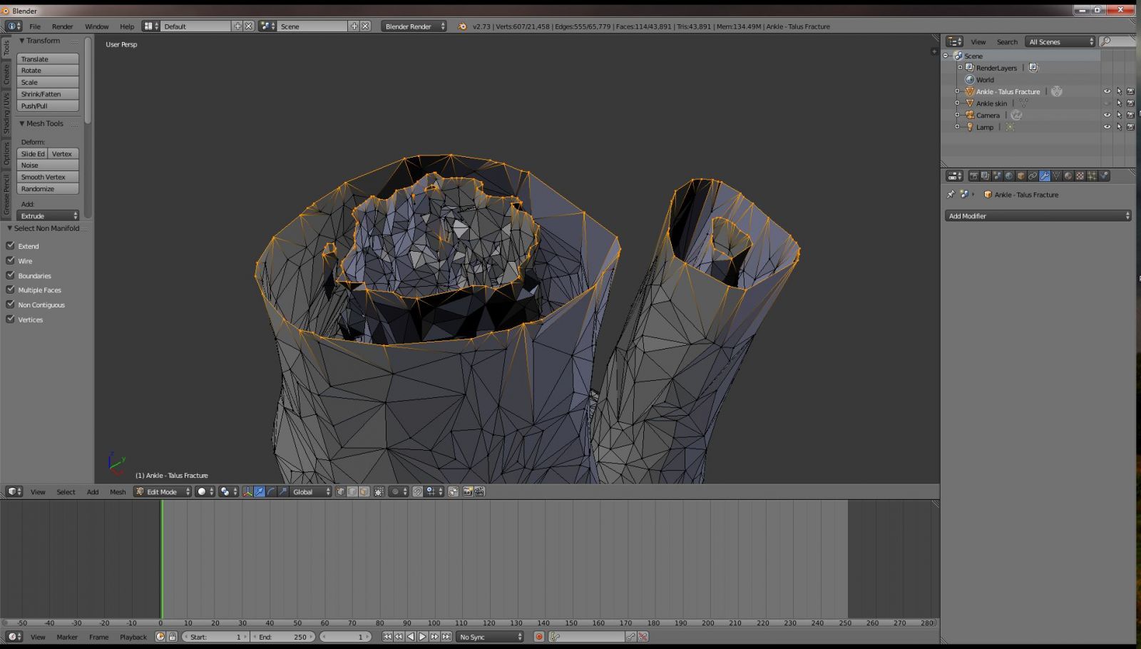
Figure 15
Go to Vertex selection mode by clicking the vertex button or hitting control-tab-1 on the keyboard as shown in Figure 16. Select one of the vertices from the medullary portion of the tibia bone as shown in Figure 17. This mesh represents the medullary cavity of the tibia bone, and is not connected to the rest of the mesh. Hit control-L to select all contiguous vertices (Figure 18). All the unwanted medullary cavity mesh should now be highlighted. Delete this by hitting the "X" key followed by the "V" key, or by hitting the delete and selecting "vertices." There is another small bit of medullary cavity mesh at the edge of the tibia cut. Perform the same routine and delete this as well.
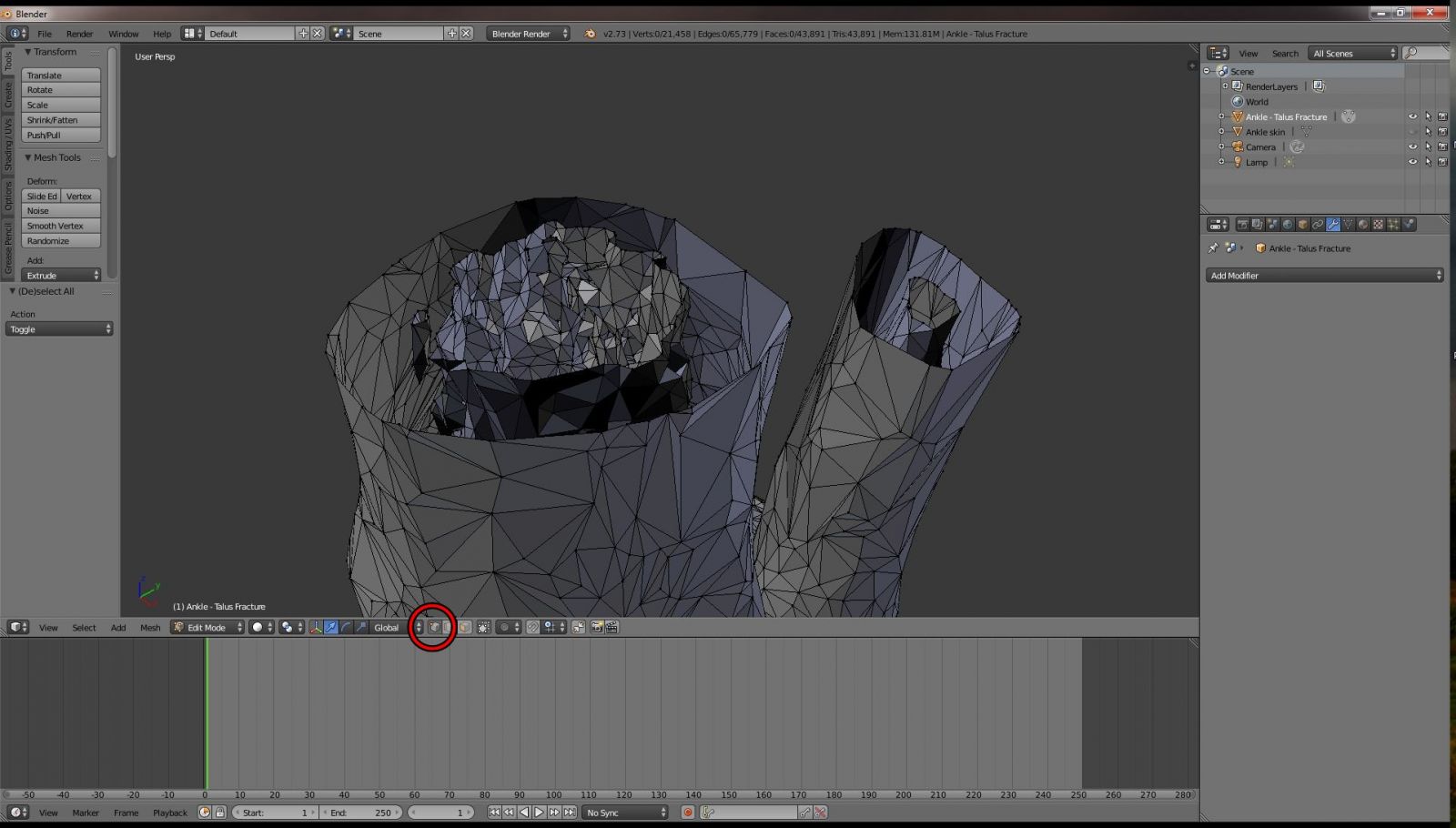
Figure 16
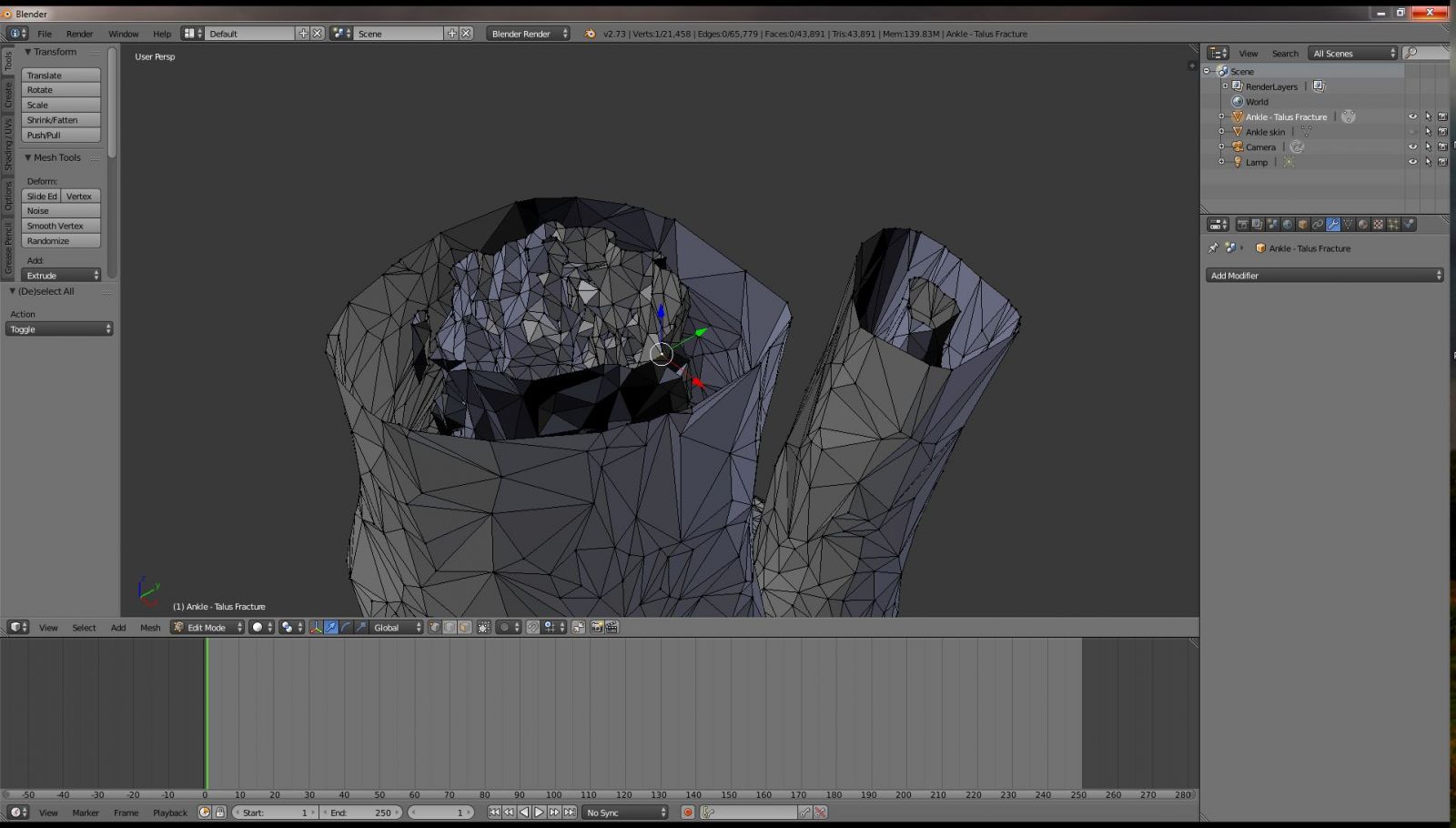
Figure 17
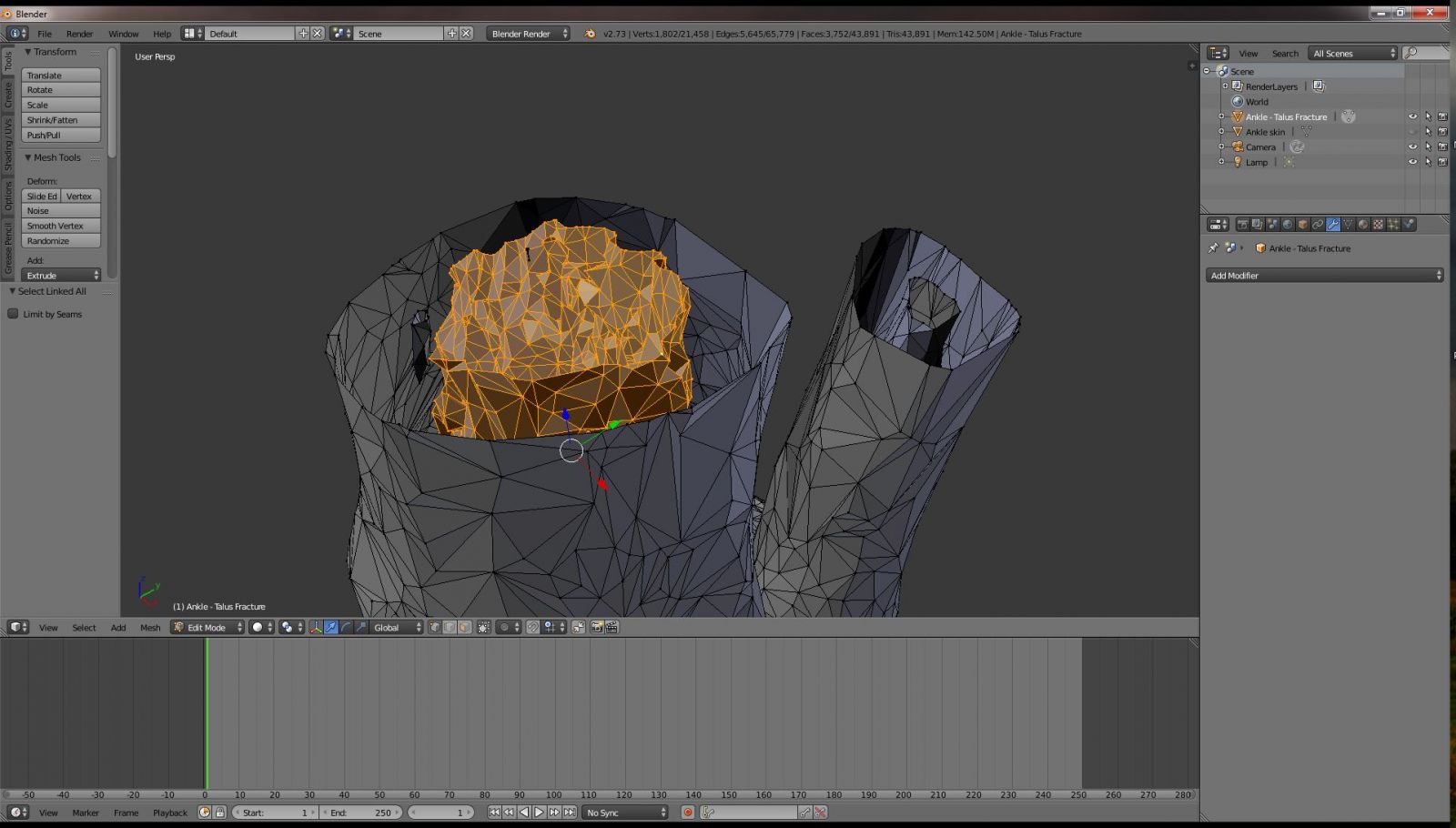
Figure 18
Next we will direct our attention to the unwanted medullary mesh of the thinner fibula bone. Click on a vertex in the fibula medullary mesh and hit control L. You will note that the entire mesh is highlighted as shown in Figure 19. This indicates that the medullary mesh is connected to the rest of the mesh in some way. We don't need to manually delete all of the medullary mesh. We just need to get it away from the edge where we will create a new face to close the bone edges. Go to Edge selection mode by hitting control-tab-2 or clicking the edge selection button as shown in Figure 20. Hit the "A" key to unselect everything. Then, click on a single edge along the unwanted medullary mesh, as shown in Figure 21.
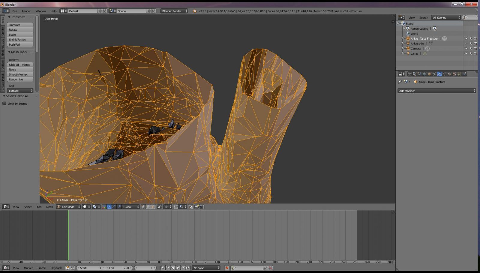
Figure 19
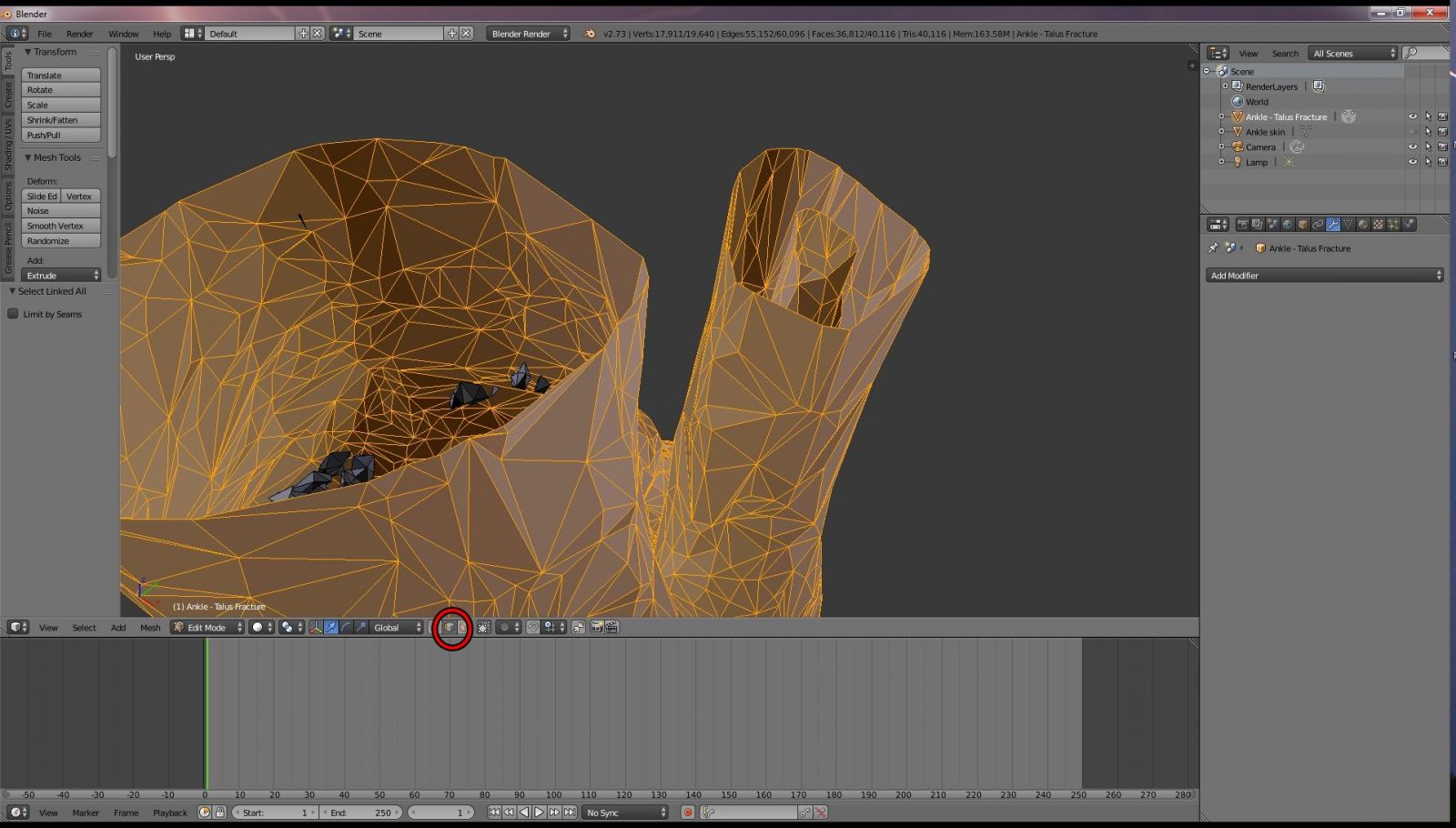
Figure 20

Figure 21
Next we will by holding down the alt key and right clicking on the edge again. Blender should select the loop around the entire edge as shown in Figure 22. We will now expand the selection by holding down the control tab and hitting the plus key on the number pad. Hit the plus key three times. Your selection should now look like that in Figure 23. Delete the highlighted mesh by hitting the "X" and "V" keys, or hitting the delete key and selecting vertices.
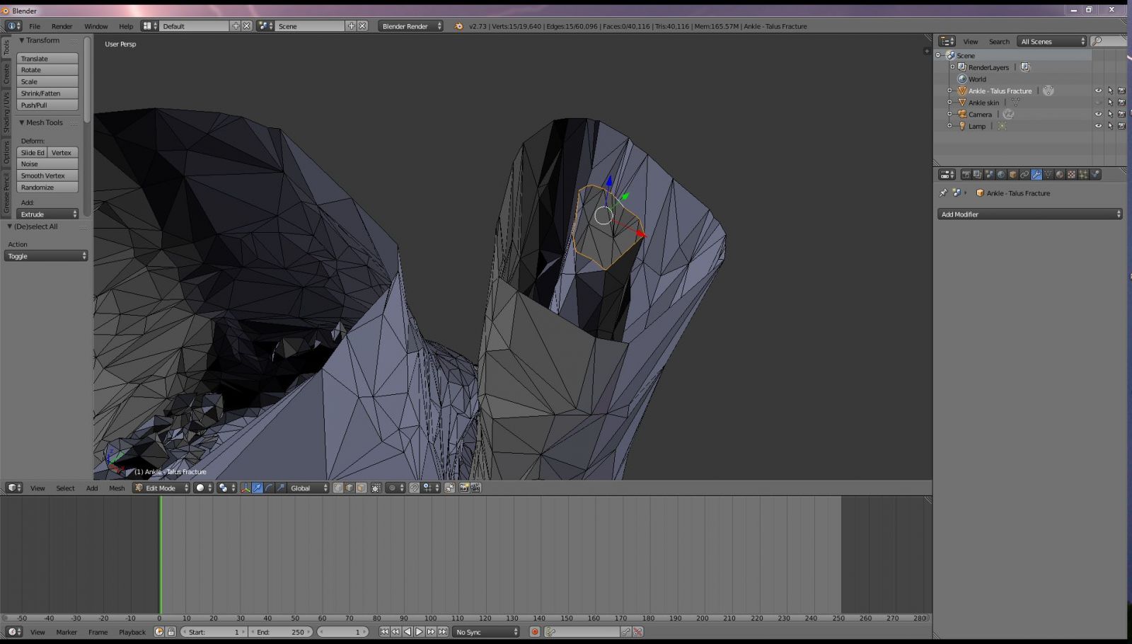
Figure 22
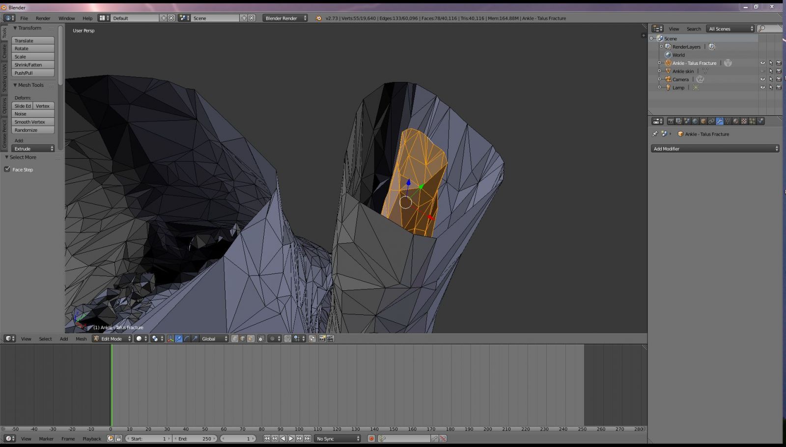
Figure 23
Next we are going to close the holes by holding down the alt key and right clicking along the edge of the cut line of the fibula. An entire loop should be selected as shown in Figure 24. Create a face by hitting the "F" key. Convert to triangles by hitting Control-T. The end of the fibula should be closed, as shown in Figure 25. Repeat the same for the open edge of the tibia bone. Afterwards the mesh should look as it does and Figure 26.
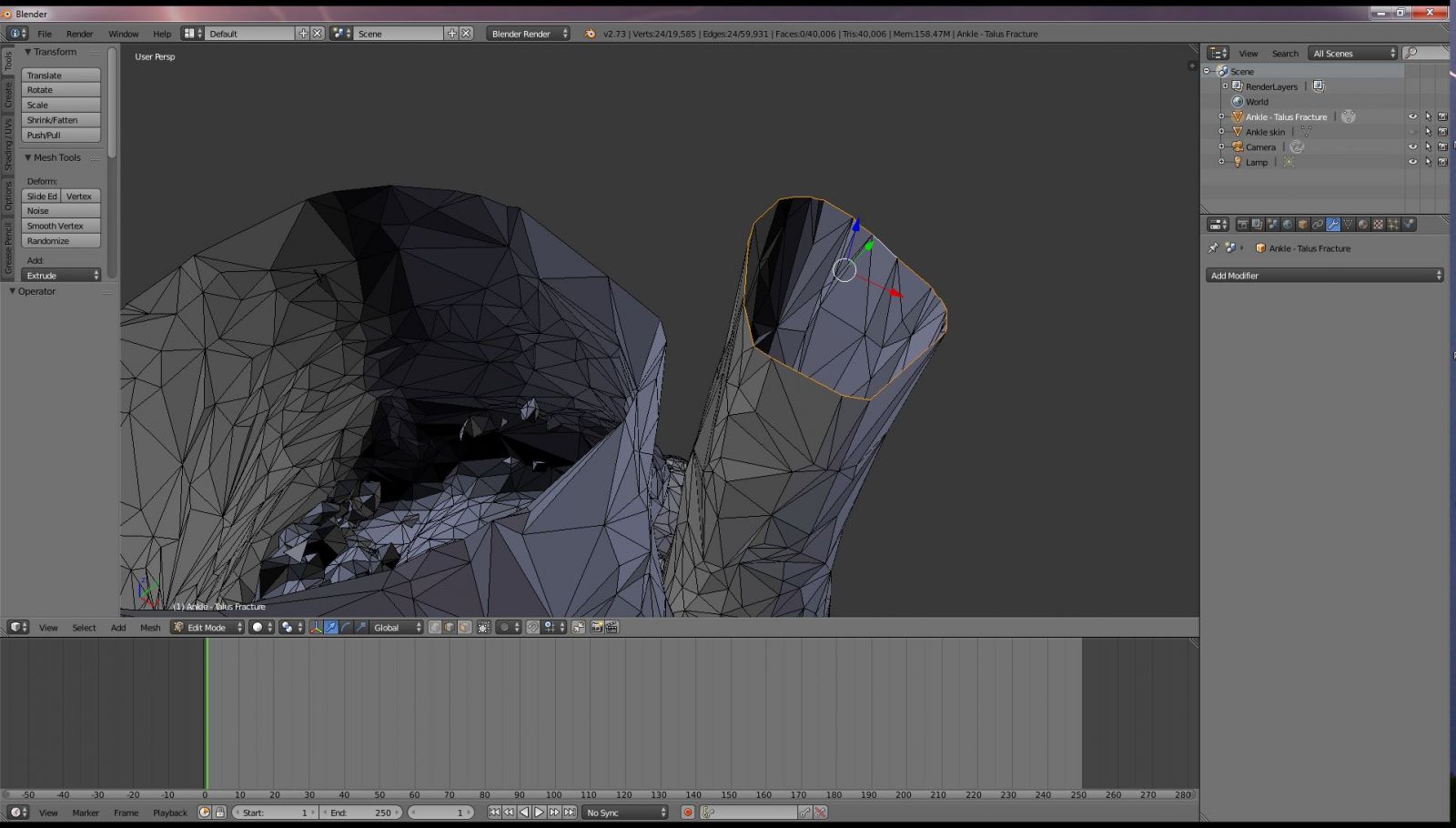
Figure 24
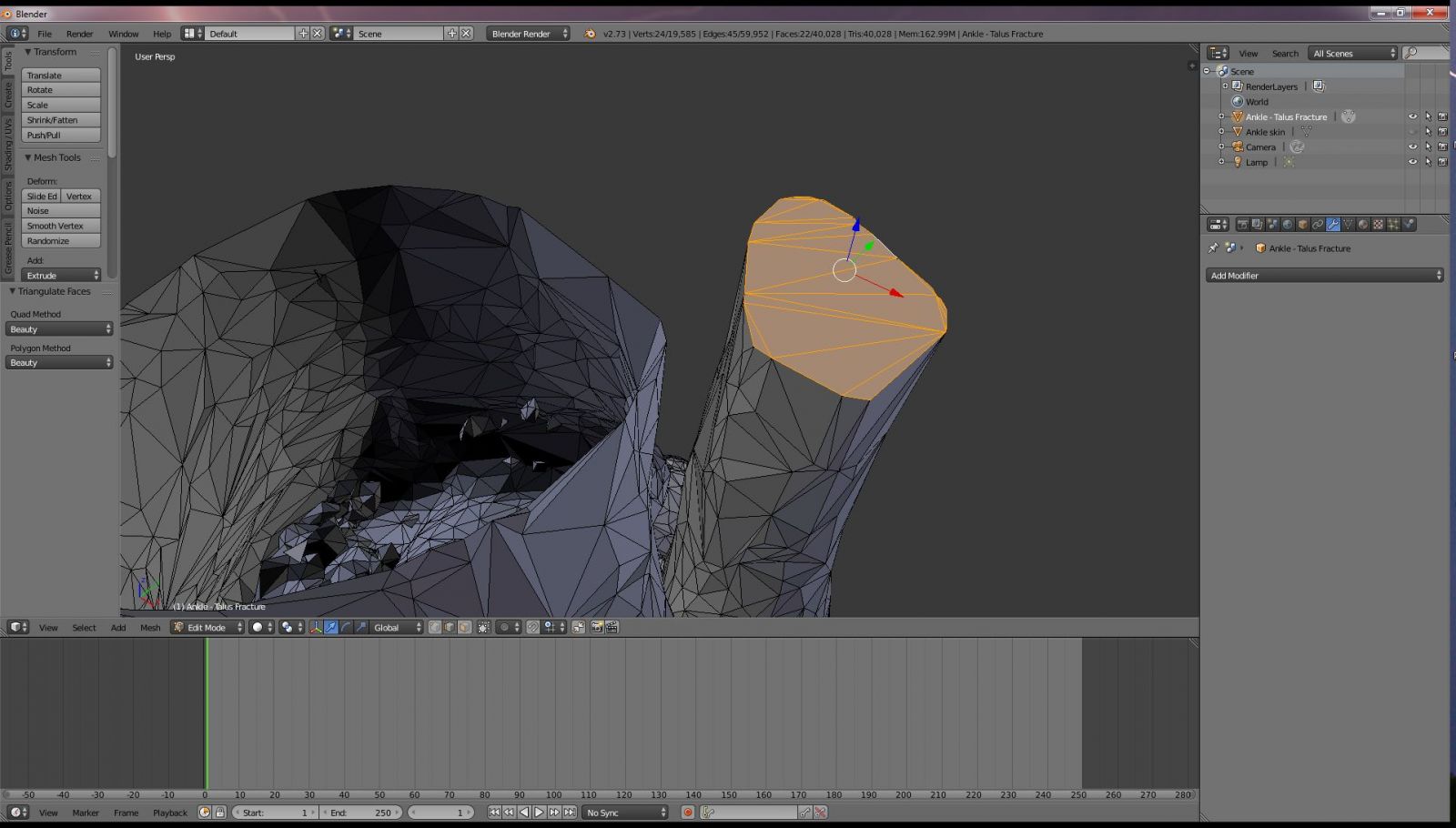
Figure 25
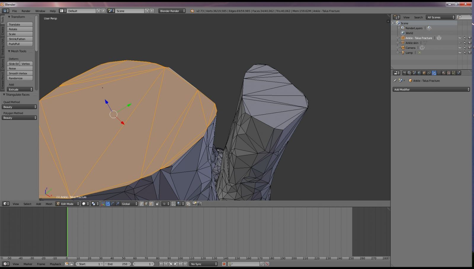
Figure 26
Creating a Shell of the model using the Shrinkwrap and Remesh modifiers in Blender
So how will it ever be possible to correct the hundreds and hundreds of mesh errors in the ankle model? This is the million-dollar question. A mesh of this complexity often cannot be fixed using automated mesh correction software, as we saw with Meshmixer. Correcting this many errors manually is a time-consuming and tedious process. I've spent hundreds of hours correcting mesh errors like this one by one. But, after years of creating 3D printable anatomical models, I've developed a technique to fix these mesh errors in only a few minutes.
The secret is this: You don't fix the mesh errors. Leave them alone. You create a new mesh to replace them!
Let's start by creating a sphere. If you are in Edit mode, exit that by hitting the Tab key. If you are still in wireframe viewport mode, hit the "Z" key to return to solid viewport shading. In the lower left-hand side of the window, hit the Add menu. Select Mesh, UV sphere and add a sphere. An "Add UV Sphere" panel will show up on the left side of your screen as shown in Figure 27. We want the sphere to have lots of detail. Under Segments enter 256. Under Rings, enter 128. The default size of the sphere is only one blender unit (1 mm) in size. This is too small, we want the thing to be huge. Enter 1000 for size. At this point you should have a very large sphere surrounding your entire scene. Believe it or not, this sphere will eventually be your new ankle object. Let's go ahead and rename it "Ankle skin" as shown in Figure 29.
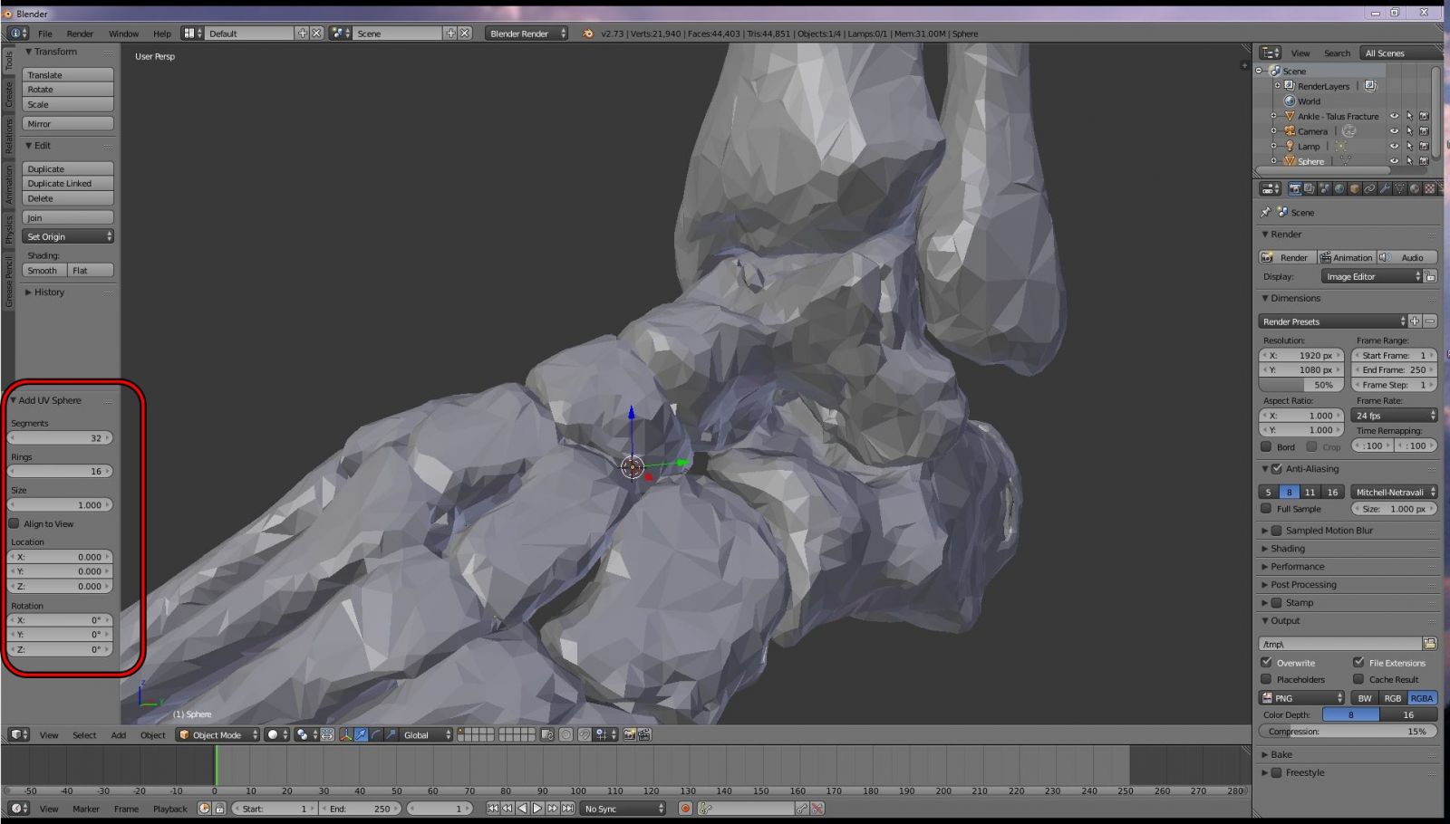
Figure 27: Add a UV sphere
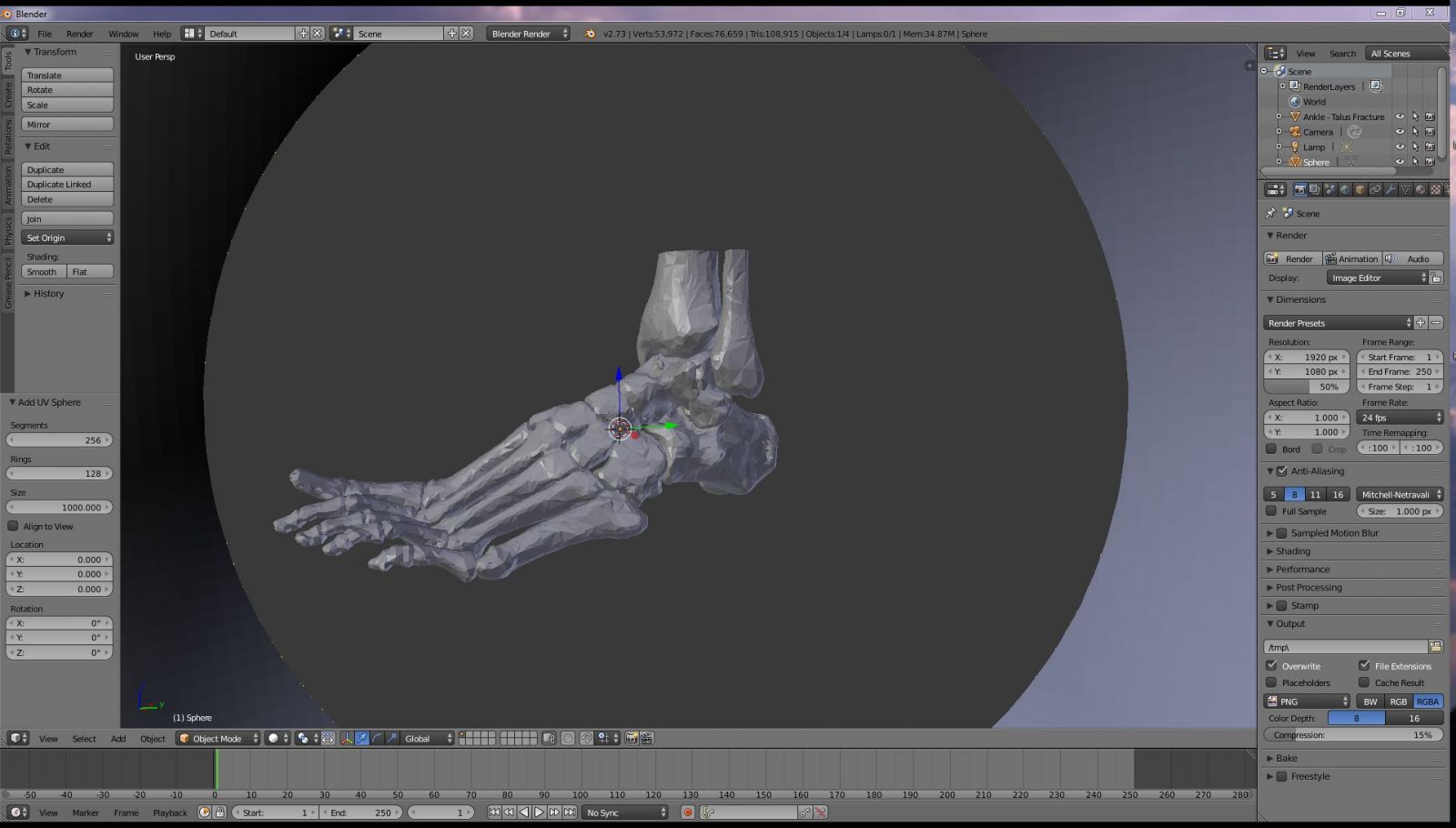
Figure 28: Configure the sphere. Segments 256, rings 128, size 1000
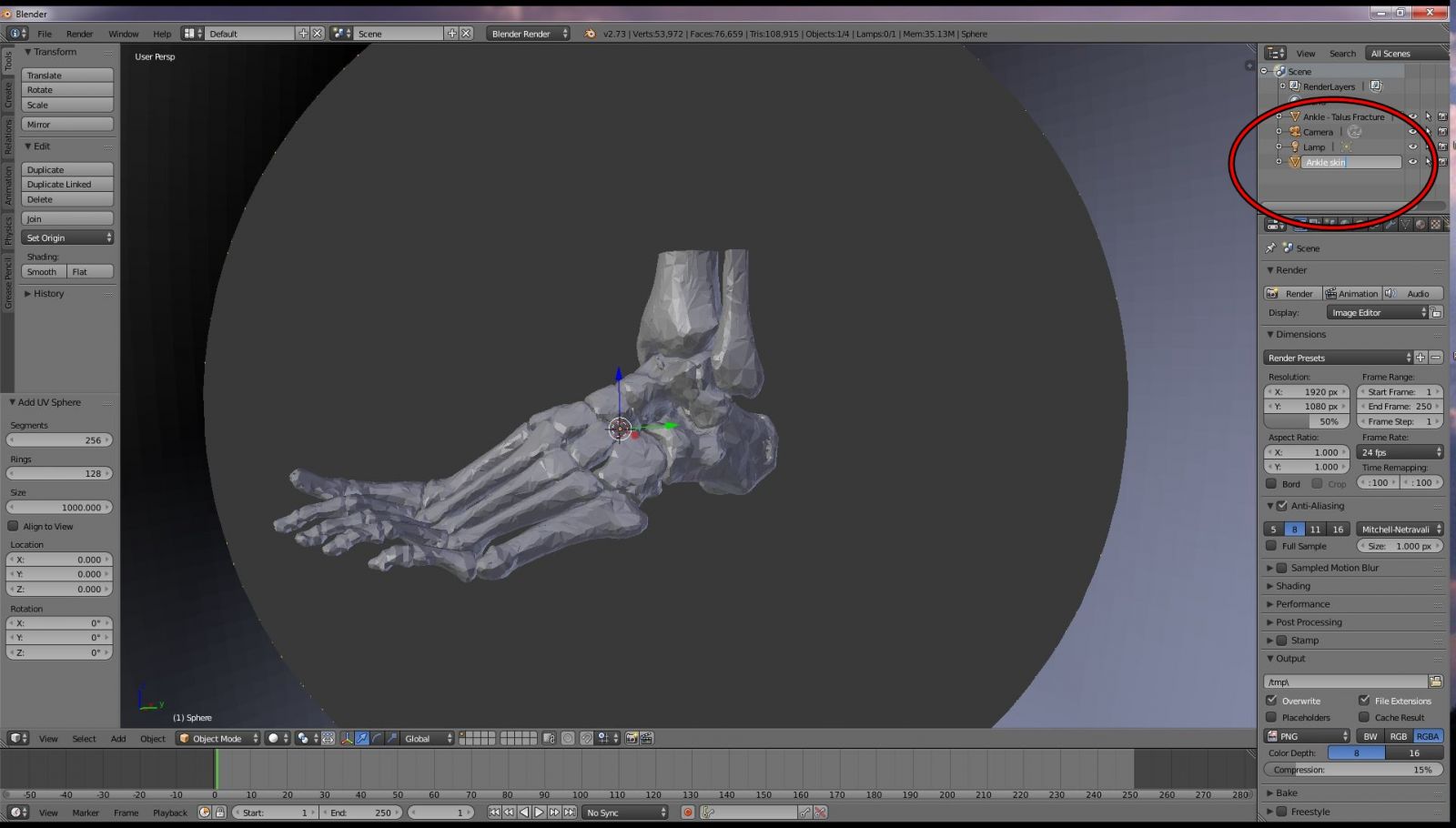
Figure 29: Rename the sphere to "Ankle skin"
Applying the Shrinkwrap Modifier
Select the "Ankle skin" object. Click on the Modifiers tab, it looks like a small wrench (Figure 30). From the Ad Modifier drop-down menu, select the Shrinkwrap item. Specify the Ankle object as "the target. Set off set to 0.5. Check the" Keep Above Surface" box. Your sphere will have shrunken down to envelop the ankle, as shown in Figure 30. Apply the modifier by hitting the "Apply" button. At this point you're thinking that your Ankle skin object hardly looks like an ankle, and you're right. If you try to apply the shrinkwrap modifier again, you won't get any change in the mesh. Blender has shrunken the sphere as best it can given the limited geometry of the sphere. To go further we need to change the geometry a bit, which is where the Remesh modifier comes in.
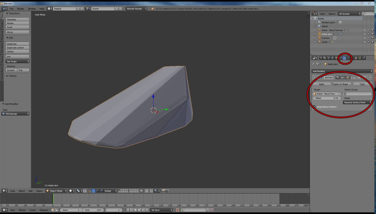
Figure 30: The Shrinkwrap modifier
Applying the Remesh Modifier
Next go to Add Modifier again, and select Remesh. Set Mode to Smooth, Octree Depth = 8, and uncheck Remove Disconnected Pieces. By now you should have something that looks like Figure 31. Apply the modifier by clicking the Apply button.
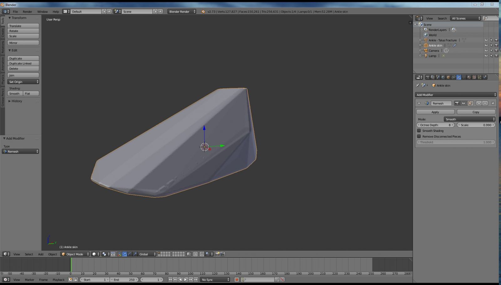
Figure 31: The Remesh modifier
Apply the Shrinkwrap Modifier again
Apply the shrinkwrap modifier again, using the same parameters as before. Your Ankle skin object should look like Figure 32. Now we are getting somewhere! There is still a long way to go, but the mesh somewhat resembles the bones of the foot. By repeatedly applying the Shrinkwrap and Remesh modifiers the Ankle skin object, which was originally a sphere, will slowly approximate the surface of the error-filled original ankle mesh. Because of the original skin was a sphere, and hence manifold, as it is shrink-wrapped around the ankle mesh it will preserve (for the most part) it's mesh integrity. There will be no unnecessary internal geometry. Any holes or other defects in the original mesh will be covered. Unfortunately, repeatedly applying the shrinkwrap and remesh modifier again and again is somewhat tedious (although not as tedious as manually correcting all the errors in the original mesh). Fortunately, we can automate this process using Python scripting. This allows us to create a new mesh in a matter of minutes.
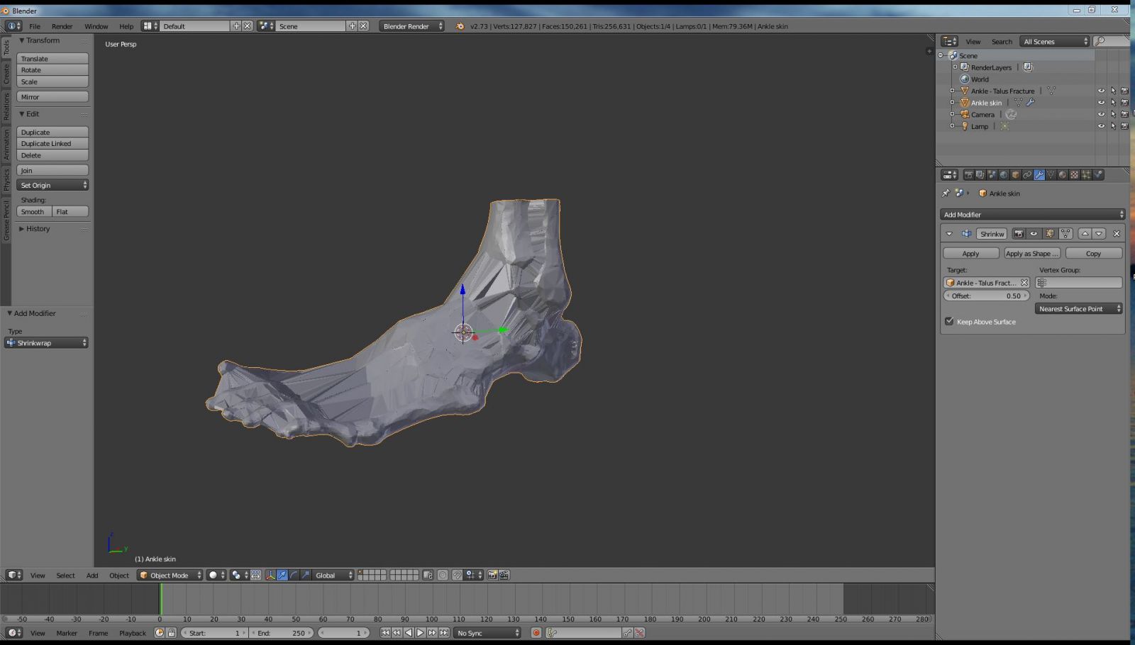
Figure 32
Automating the Shrinkwrap Process using Python Scripting
For those of you less familiar with Blender's more advanced features, you may be surprised to learn that it is fully scriptable. That means that you can program it to perform tasks repeatedly using a Python script. In this case we want to repeatedly execute shrinkwrap and remesh modifiers on our ankle skin object. With each iteration the skin will more closely approximate the surface of the original mesh. If you are familiar with Python scripting, you can write a script yourself to call the necessary modifiers and specify the necessary variables. To make things easier for you, I have written a Python script for you. It is included in the free tutorial file pack.
Change the bottom window to the text editor. View button in the bottom left-hand corner as shown in Figure 33. Select Text Editor. Click on the "Open" button and navigate to the folder with the tutorial file pack files as shown in Figure 34. Double-click on the "shrinkwrap loop.txt" file as shown in Figure 35.
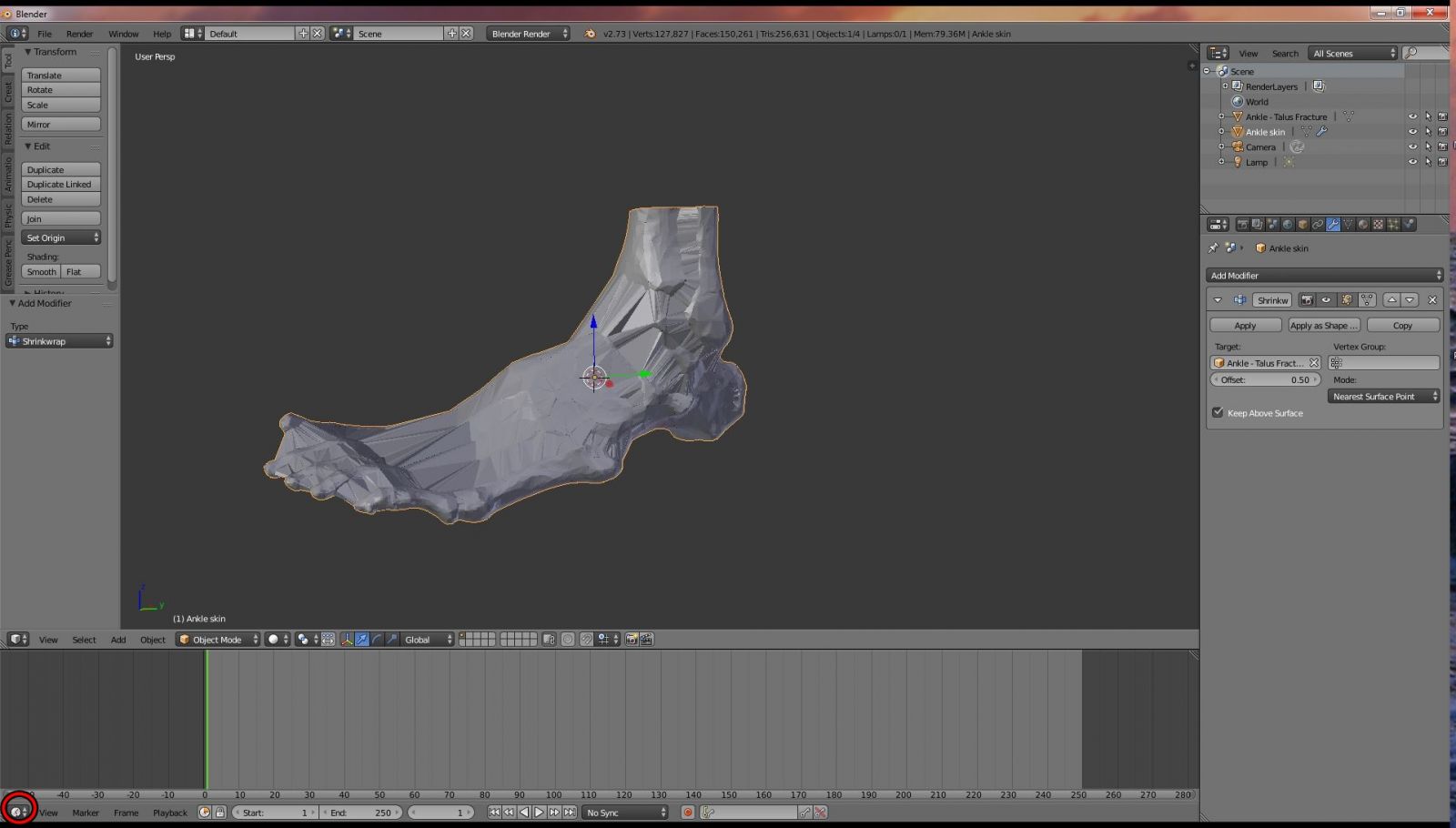
Figure 33: Select the text editor
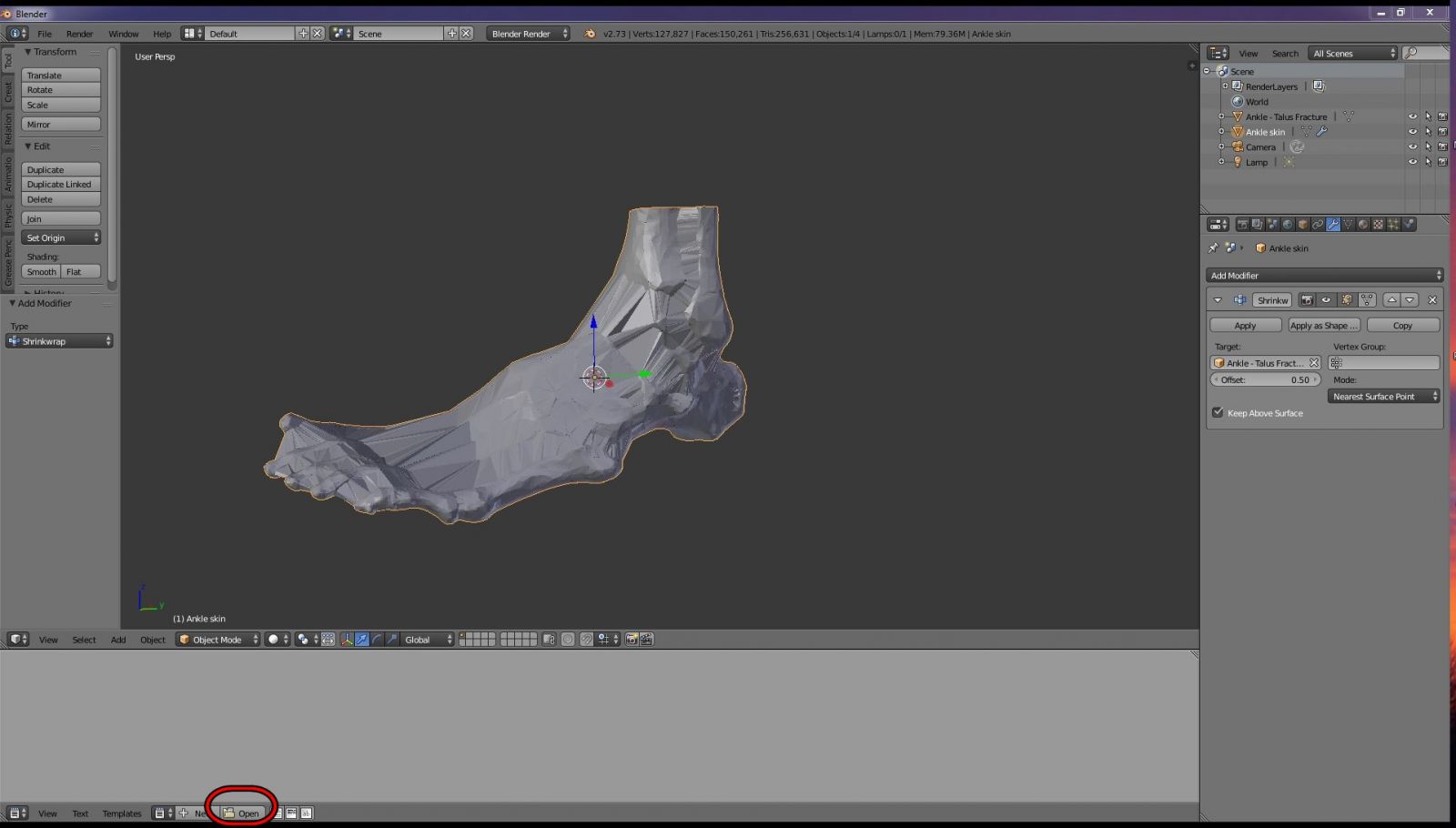
Figure 34: Click on the Open button
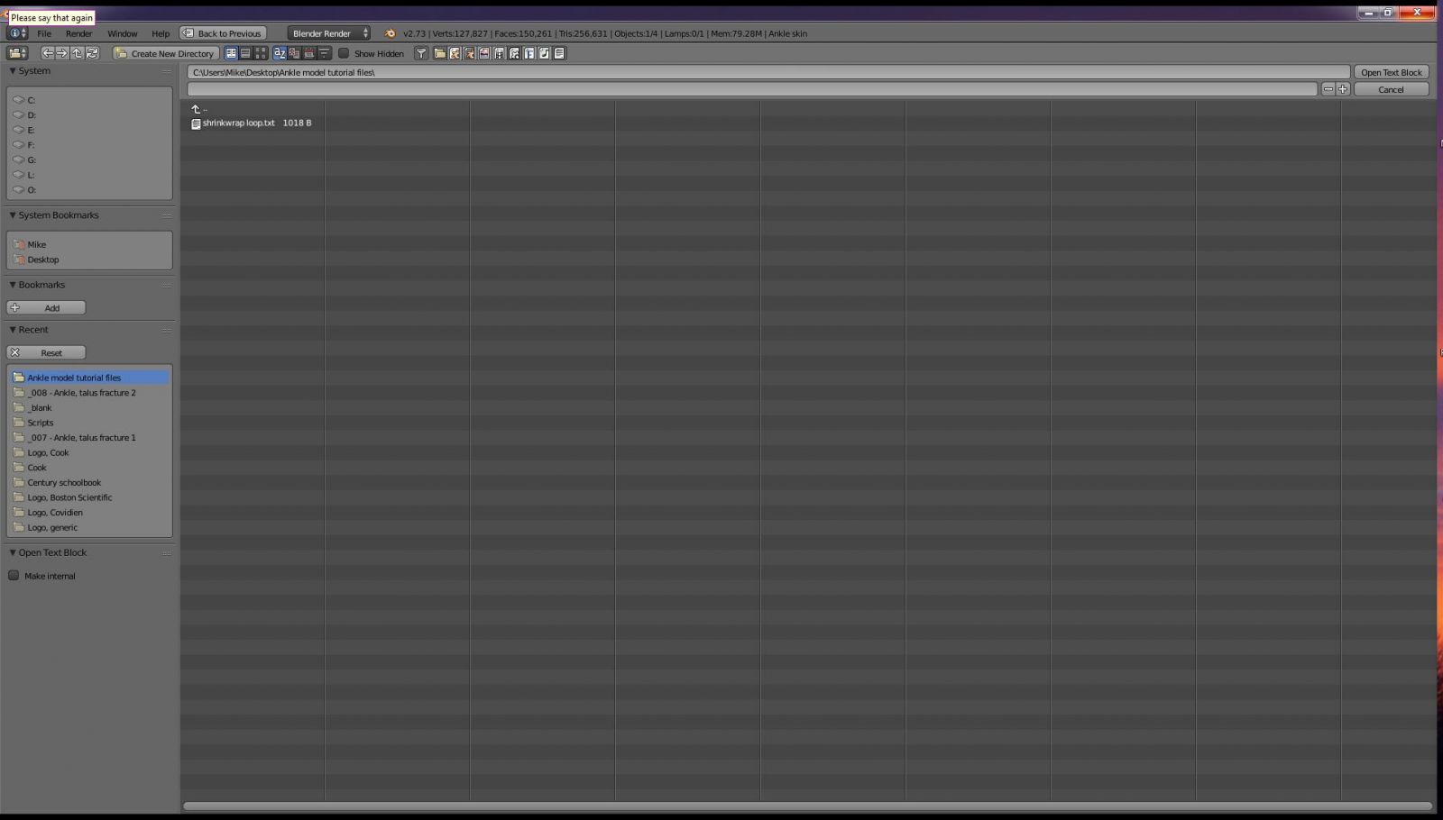
Figure 35: Open the "shrinkwrap loop.txt" file
The script file should now open in the text editor window. Adjust the target_object variable to be the target you want your skin wrapped around, in this case the "Ankle - Talus Fracture" object. Leave the shrinkwrap_offset variable at 0.5 for now. You can specify how many shrinkwrap-remesh iterations you want to run. For now leave it at 20. Click the "Run Script" button as shown in Figure 36. The script will now run, and it will apply the shrinkwrap-remesh modifiers 20 times. On my machine it takes about one minute for the script to execute.
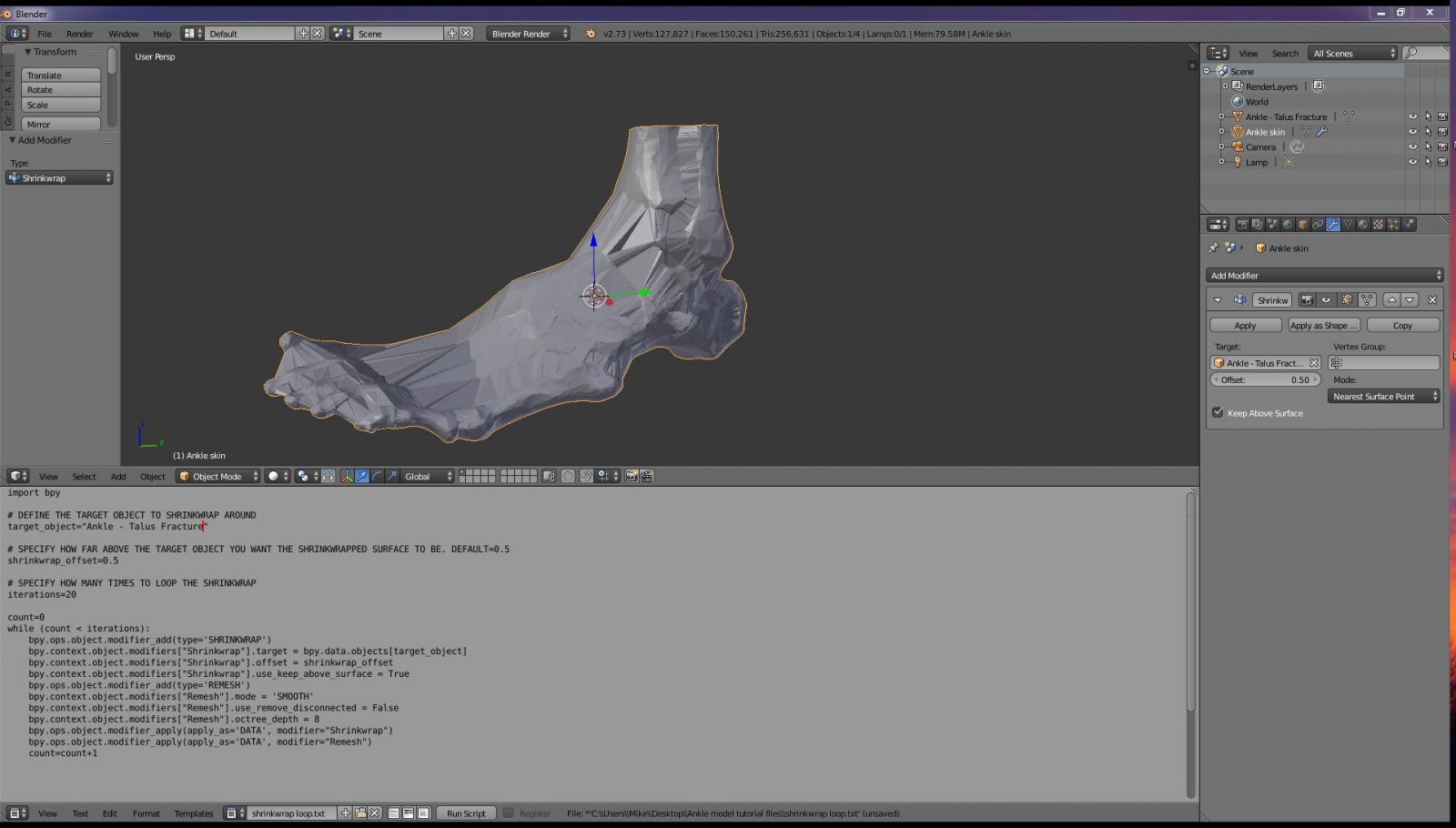
Figure 36
At this point you'll notice that the ankle skin object very closely approximates the original ankle object, as shown in Figure 37. Run the script again using the same settings. At this point the mesh is really looking pretty good. Let's run the script a final time with the smaller offset to more closely approximate the real bones. Set the shrinkwrap_offset variable to 0.3 and run the script again reducing iterations to 10. After completion the mesh should appear as it does in Figure 38. If you compare our new skin mesh as shown in Figure 39 (left) to the original ankle object in Figure 39 (right) you can see that our new skin is actually much more realistic than the original mesh. The highly faceted appearance of the original mesh has been replaced by a smoothed appearance of our shrink-wrapped skin. Furthermore, whereas the original mesh actually had separate bones that were disconnected, the new, shrink-wrapped mesh is a single interconnected object. From a 3D printing standpoint this is much better as the ankle bones will print together as a single unit
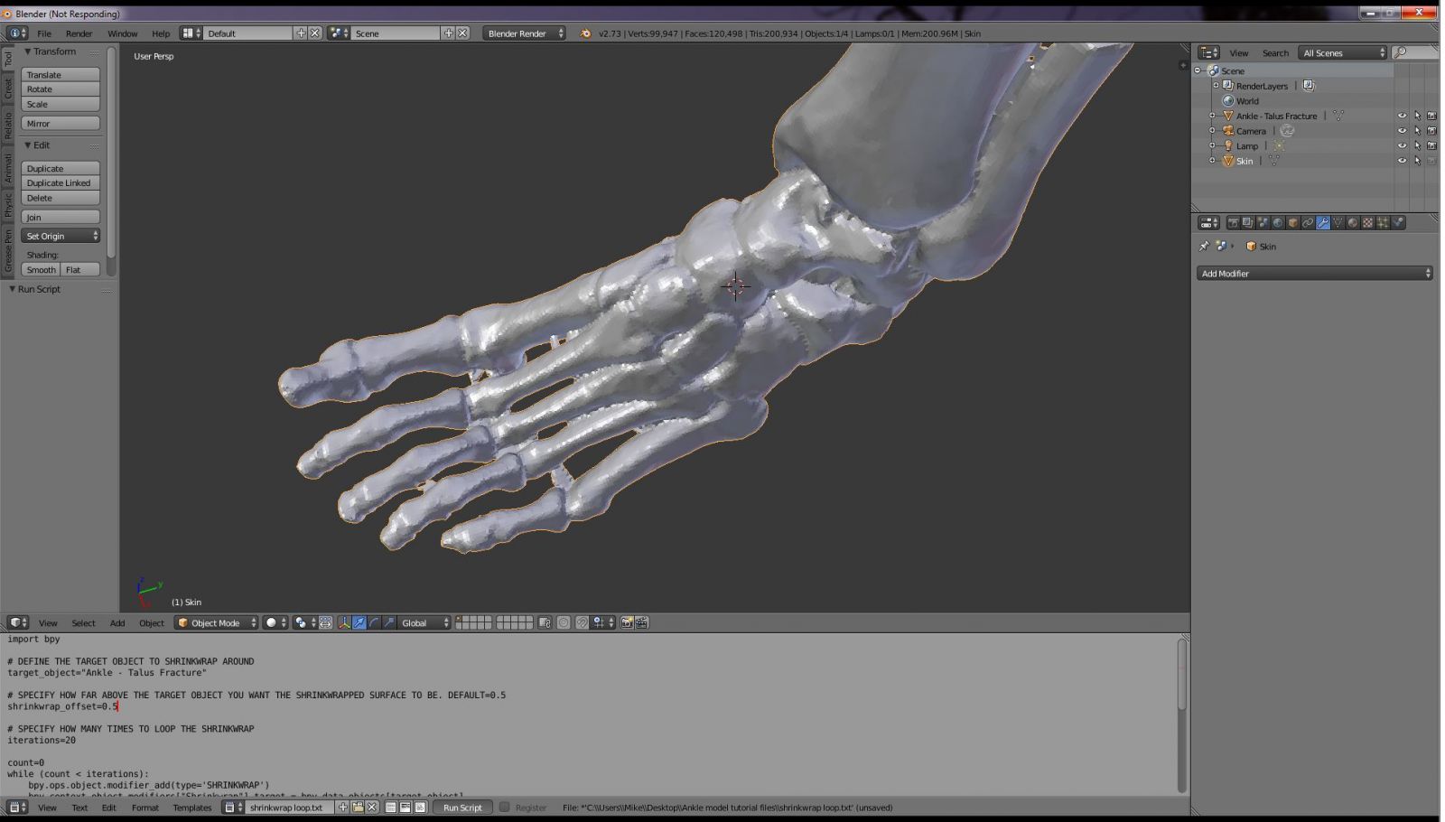
Figure 37
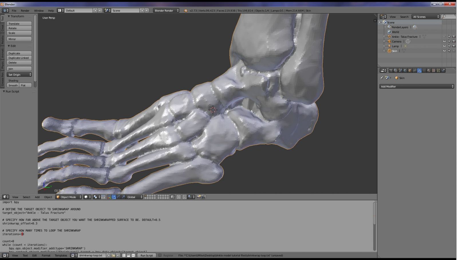
Figure 38
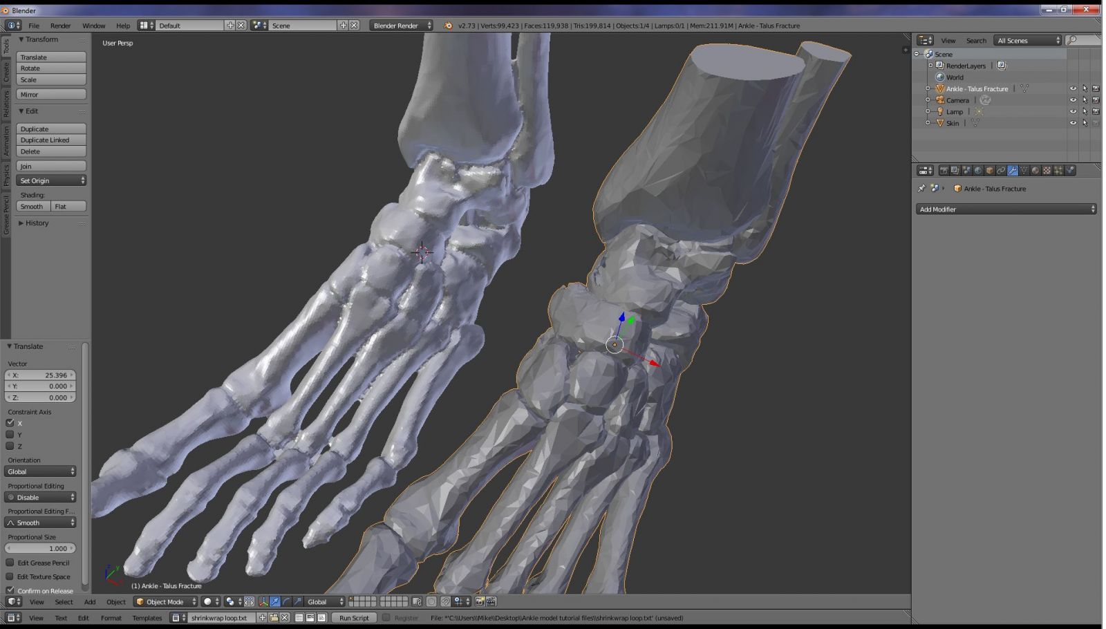
Figure 39: Comparison of original plus new shrink-wrapped mesh.
Finalizing the Ankle Model for 3D printing using Meshmixer.
Select the new ankle object. Export the object to the STL file format. From the file menu select Export and then "Stl (.stl)." Let's call the file "ankle corrected.STL." Open the new STL file in Meshmixer. You will notice that Meshmixer immediately identifies some mesh errors as shown in Figure 40. This is because the Remesh modifier in Blender occasionally introduces non-manifold mesh defects. You will note however that the number of defect is significantly less than our original model which was shown in Figure 1. With this smaller number of errors, Meshmixer can fix them automatically. Go to the Analysis button and select Inspector. Meshmixer will highlight the individual mesh defects, as shown in Figure 41. Click on the "Auto Repair All" button. Meshmixer will then automatically repair the mesh defects. The result is shown in Figure 42.
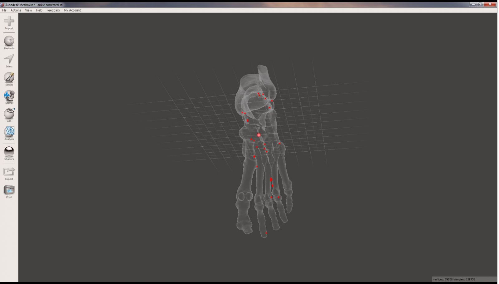
Figure 40
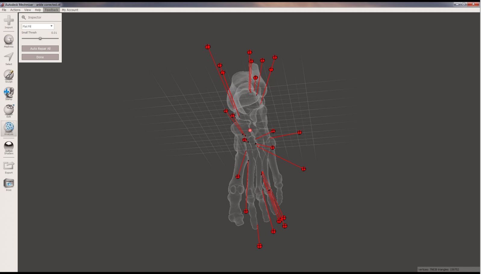
Figure 41: Meshmixer inspector
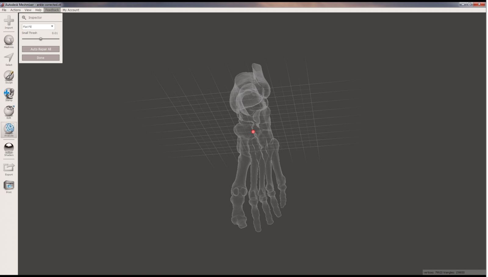
Figure 42: Corrected mesh
The mesh looks great, and is ready for 3D printing! Export the STL file by going to the File menu in Meshmixer and selecting Export. Save the file as "ankle final result.STL".
Please share with the community.
If you have found this tutorial helpful and are actively creating 3D printable anatomic models, please consider sharing your work with the Embodi3D community. You can share your models in the File Vault. If you have comments or advice, you can share your expertise in the Forums. If you are interested in blogging about your adventures in medical 3D printing, contact me or one of the administrators and we can set up blogging on your Embodi3D user account. If you wish to hire someone to help you with your anatomical 3D printing project, you can place an ad for free in the Services Needed Forum, If you are doing your own anatomical 3D printing and are willing to help others, list your services for free in the Services Offered Forum.
This is a community. We are all helping each other. Please consider giving back if you can.
Have fun 3D printing!
- Dr Javier R, Kendell, vlad and 1 other
-
 4
4


7 Comments
Recommended Comments
Create an account or sign in to comment
You need to be a member in order to leave a comment
Create an account
Sign up for a new account in our community. It's easy!
Register a new accountSign in
Already have an account? Sign in here.
Sign In Now