
Choosing the Best Medical Imaging Scan to Create a 3D Printed Medical Model

Entry posted by Dr. Mike ·
27,977 views

Hello, it's Dr. Mike here again with another tutorial on medical 3D printing. In this tutorial we are going to learn what types of medical imaging scans can be used for 3D printing. We will also explore the characteristics those scans must have to ensure a high quality 3D print. This is one of a series of 3D printing tutorials that will teach you how to create 3D printed anatomical and medical models yourself. Open source and commercial software are covered in the tutorials along with 3D printer selection and setup. This tutorial is followed by a tutorial on Creating 3D Printable Medical Models in 30 minutes using free software: Osirix, Blender, and MeshMixer.
Introduction to Selecting a Medical Scan for 3D Printing
If you listen to the hype in the press, it sounds like any medical imaging scan can be easily converted into a high quality 3D printed anatomic model, and any structure of interest can be shown clearly and beautifully. This is simply not true. In fact, most conventional medical imaging scans are not suitable for 3D printing. Those few that are suitable will probably only produce high-quality 3D prints of a few anatomic structures. In this tutorial I will go over the basic elements that make a medical scan suitable for 3D printing. I will briefly discuss different imaging modalities such as CT, MRI, and ultrasound. By the end of this tutorial you should be able to recognize whether a medical scan is suitable for 3D printing. If you are planning on having a medical scan done with the intention of 3D printing from the scan, you will be able to protocol the scan appropriately to enable a high quality 3D print.
Imaging planes
I'd first like to take a moment to discuss the standard imaging planes used in medical scans. When a medical scan is performed, images of the body are usually captured and displayed in one of three standard imaging planes. These are the transverse plane (also called axial plane), the coronal plane, and the sagittal plane. Figure 1 demonstrates these planes. In layman's terms, the axial plane divides the body into top and bottom, the coronal plane front and back, and the sagittal plane right and left. CT and MRI scans are typically comprised of several series of images. Each series is comprised of a stack of images in the same plane spaced out evenly. When a medical scan is converted into a format suitable for 3D printing, such as an STL file, the computer takes this stack of images and extrapolates the volume of an object. A surface is then calculated around that volume. That surface is what becomes the 3D printed model.
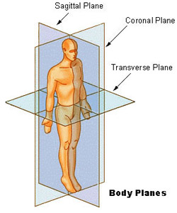
Figure 1: Standard imaging planes used in medical scans. Source: National Cancer Institute
Imaging Modality: CT versus MRI versus ultrasound
In order to understand what scans are best used for 3D printing, a very basic understanding of the types, or modalities, of medical scans is needed. The medical physics behind how these scans work can literally fill volumes. Radiology residents are required to take board examinations on the physics and engineering of medical scanners as part of their training. I will attempt to summarize only the most critical information about medical scans into a few short paragraphs to get you up and 3D printing as quickly as possible.
Computed Tomography, or CT scans, are created when an x-ray beam is rotated around the patient. An x-ray detector on the opposite side of the emitter records the strength of the beam that emerges from the other side of the patient. Knowing the angle and position of the x-ray emitter and the strength of the beam emerging from the other side of the patient, a computer can calculate the x-ray appearance of the body in three dimensions. An x-ray beam is generally absorbed or deflected by electrons in matter. Since the density of electrons in matter is more or less the same as the actual physical density of matter, a CT scan can be considered to be a density map of the patient. Things that are dense, such as bone or metal, will appear white. Things that are not dense, such as air, appear black. Figure 2 shows how the different densities of tissue appear on a standard CT scan. When intravenous contrast is given, which contains an iodine-containing chemical that is very dense, it appears white. Fat is not very dense and floats on water, thus it has a blackish appearance.
What else floats on water? Choices: bread, apples, very small rocks, cider, gravy, cherries, mud, churches, lead, a duck. (This is a joke. If you get the reference, please leave a comment and give yourself a star).
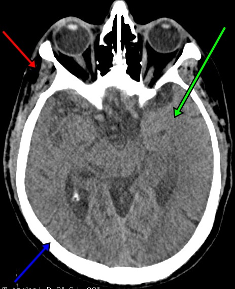
Figure 2: Effect of tissue density on CT scan appearance. This CT scan image of the head at the eyes shows fat in the temporal fossa as black (red arrow), intermediate density brain tissue as gray (green arrow) and dense calcium-laden bone in the skull as white (blue arrow).
Magnetic Residence Imaging, or MRI, is a type of imaging that uses very strong magnetic fields to generate an image. The hydrogen atoms that are part of almost all biological structures (water, fat, muscle, protein, etc.) align with the magnetic field. Radio waves can be sent into the scanner causing the hydrogen atoms to flip orientation. When the radio waves are turned off, the hydrogen atoms flip back and emit their own faint radio signal. Based on analysis of these faint radio emissions and by varying the magnetic field strength and timing of the radio wave pulses, a variety of images can be generated. These different pulse sequences can be used to highlight different types of tissue.
Take Figure 3 for example. Four different pulse sequences are shown of the same slice of brain: T1, T2, FLAIR, and T1 with gadolinium contrast. On the T1 image tissues with fat are a bright white, as shown by the fat in the skin (white arrow). The hard, calcium-filled tissue of the skull is black, with the exception of a small amount of bone marrow which is gray in color and sandwiched between the inner and outer skull plate (yellow arrow). The watery cerebral spinal fluid in the lateral ventricles are black (red arrow). However, on the T2 image the watery cerebral spinal fluid is bright white (red arrow). T2 images show water very well. In addition to the water in the ventricles, swelling of the brain tissue due to an adjacent brain tumor can be seen as a white appearance (blue arrow). FLAIR images are similar to T2 images except pure water has been subtracted from the image. Thus tissue swelling (blue arrow) is still clearly visible but the cerebral spinal fluid in the ventricle (red arrow) now appears black. Finally, in the T1 images with gadolinium IV contrast small blood vessels are visible. Additionally, you can actually see the brain tumor and meninges turning white from contrast enhancement (purple arrows).
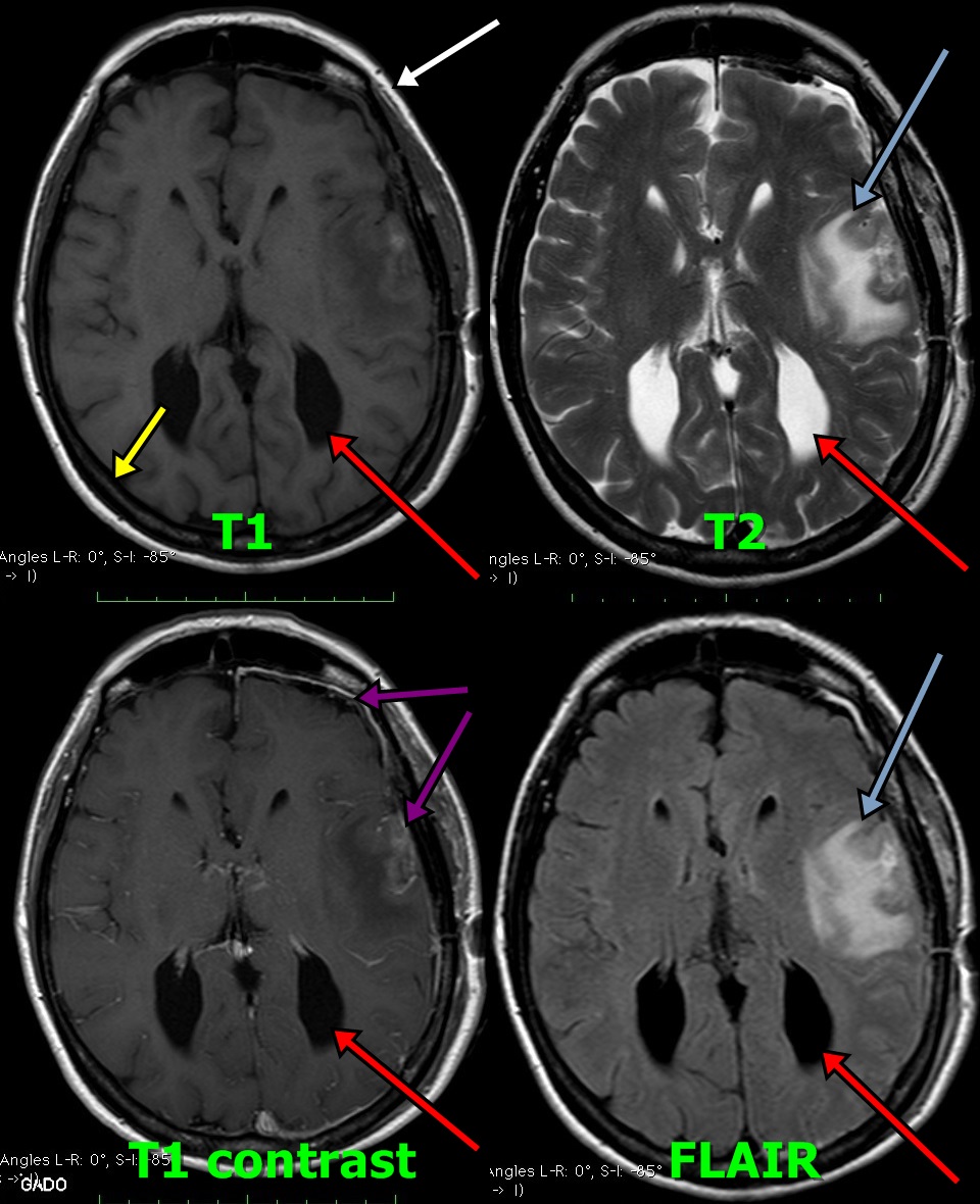
Figure 3: MRI of the brain at the same level using four different pulse sequences. The patient has a left frontal lobe brain tumor.
When 3D printing from an MRI scan, it is important to select images from a pulse sequence that will highlight the structure you wish to visualize. Arteries, tumors, body fluid, bones, and general tissue are all best seen on different sequences. If you choose the wrong imaging sequence to generate your 3D model from, you will encounter only frustration.
Ultrasound images are generated when soundwaves are sent into the body by an ultrasound emitter. The waves then bounce off various structures and are detected by a receiver, typically built into the emitter. The concept is similar to sonar that is used on ships and submarines. Based on the strength and depth of the soundwave return, an image can be created. Ultrasound images can be used for 3D printing, however it is very difficult to do so because individual images are not registered in a fixed place in space. The images are acquired by sliding the ultrasound transducer on the skin. The exact location in space and angle of the transducer at the time of image acquisition is not known, which makes generation of a 3D volume difficult or impossible. In general, ultrasound is not recommended as a source of imaging data for 3D printing for the beginner.
Key features of medical imaging scans used in 3D printing
There are certain features common to all scan modalities that can help you to create a good 3D print. When considering making a 3D medical or anatomic model you must first decide what you want the model to show. Should it show bones, arteries, or organs? Having a model with unnecessary structures included not only makes it more difficult to manufacture, but it also diverts attention away from the important parts of the model. Give this careful thought. Once you have decided what you want to show, evaluate the medical scan you want to create your model from carefully. If the scan doesn't have the proper characteristics, you can exponentially increase the difficulty of getting a 3D printable model from it.
1. Presence of Intravenous contrast
Take a look at these two axial (transverse) images from CT scans of the upper abdomen (Figure 4). Both images show slices of the upper abdomen at the level of the tops of the kidneys and liver. What is the difference between the two? You'll notice that on the rightmost scan the aorta is white, whereas on the left scan the aorta is gray. Figure 5 is a zoomed image of this region and shows this in more detail. This is because the rightmost scan was performed with intravenous contrast and that contrast is causing the aorta and other vessels to turn a bright white color.
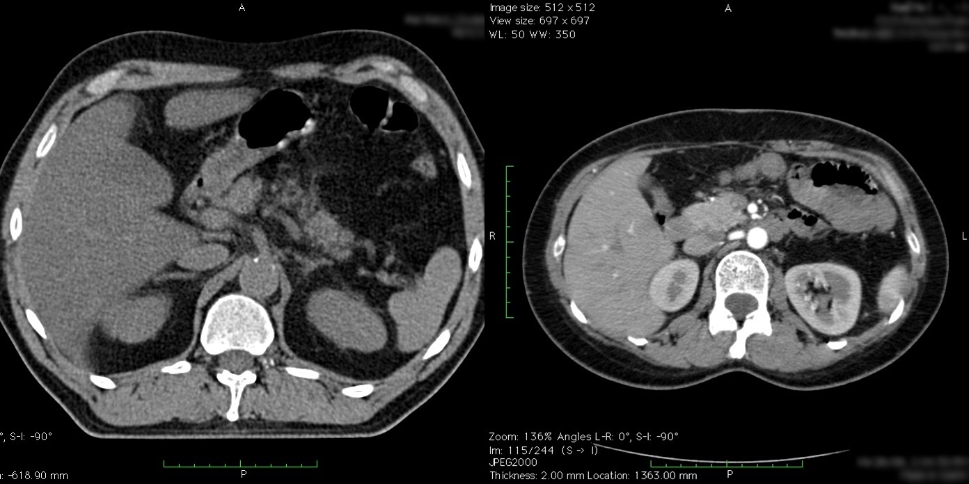
Figure 4: The effect of intravenous contrast.
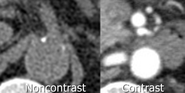
Figure 5: Close-up view of the abdominal aorta with (right) and without (left) intravenous contrast.
Take a closer look at the kidneys. Figure 6 shows a zoomed-in image. The outer part of both kidneys on the contrast-enhanced scan on the right are a light shade of color. This is due to blood mixed with contrast going into the outer cortex of the kidney. With the contrast-enhanced scan you can clearly see the edge of the kidney, even where it touches the liver. On the noncontrast scan the border of the kidney is only discernible where it is adjacent to the darker colored fat. Where it touches the liver it is difficult to see where the kidney ends and the liver begins. If you want to make a print of the kidney, it will be very difficult to discern the edge of the kidney without IV contrast.
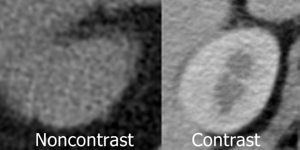
Figure 6: Close-up view of the right kidney with (right) and without (left) intravenous contrast.
If you are trying to create a 3D printed model of a bone, it is best to create it from a scan without IV contrast. This is because the bone is the only thing that will be a white color in the scan. This allows your software to easily separate the bones from other tissues. The presence of intravenous contrast may trick the software into thinking that blood vessels or organ tissue is actually bone, and it may improperly include these structures in the 3D printable surface model. These unwanted structures can be manually removed, but this can be an incredibly time-consuming and laborious exercise. It is best to avoid this problem in the first place.
On the other hand, if you are trying to 3D print a blood vessel, tumor, or organ, then intravenous contrast is absolutely necessary. Vessels and tumors will light up, or enhance, with IV contrast, turning white on a CT scan. Which will make separation of these structures from background tissue more easy to perform.
2. Timing of intravenous contrast
If you are creating a 3D printed model of a blood vessel, tumor, or organ, merely having intravenous contrast in your scan is not sufficient. You also must have the proper contrast timing. Contrast injected into a vein before a medical scan is not static. It is a very dynamic entity, and flows through the blood vessels and tissues of the body at different times before being excreted by the kidneys.
Intravenous contrast is injected through an IV catheter, typically in the arm immediately before initiation of scanning. The contrast flows with the blood into the superior vena cava, the large vein in the chest, and then into the heart where it is then pumped into the pulmonary arteries. It is at this point, typically about 15 to 20 seconds, that is the best time to perform a scan to clearly visualize the pulmonary arteries. The contrast-filled blood then flows out of the lungs back to the heart where it is pumped into the aorta and its branches. This may be about 30 seconds after contrast injection, and is the best time to see the arteries. The contrast-filled blood then percolates into the capillaries of the tissues throughout the body. This is the point of maximal tissue enhancement, and is usually the best time to see tumors and organs. The blood then leaves the tissues and drains back into the veins, which is the best time to look at the veins. Finally, after about five minutes or so, the contrast begins to be excreted by the kidneys into the urine, and can be seen within the collecting system of the kidneys, the ureters, and the bladder.
Take a look at Figure 7. When the scan was performed in the arterial phase (left) you can clearly see the aorta, arteries of the intestine, and outer rim (cortex) of the kidneys have turned white with contrast-enhanced blood (green arrows). After about five minutes the scan was repeated (right), and on these delayed phase images only a small amount of contrast is left within the aorta and blood vessels. However, contrast can be seen concentrated within the central portions of the kidney (red arrow). This is urine mixed with contrast collecting in the renal pelvis and ureter.
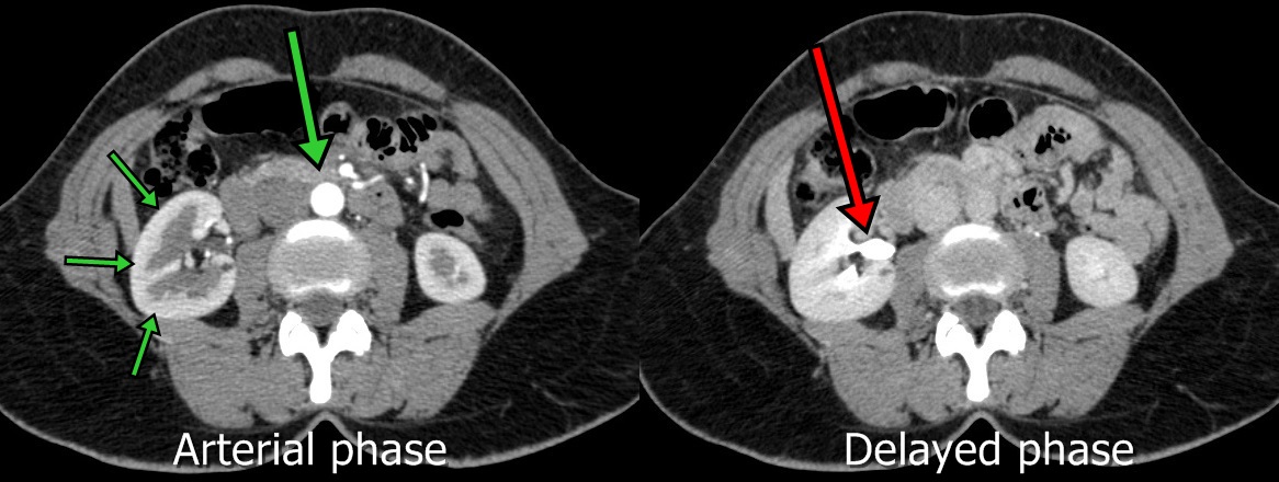
Figure 7: Transverse (axial) images from a contrast-enhanced CT scan from a patient with intravenous contrast in the arterial (left) phase and delayed urographic (right) phase.
The point I'm trying to make here is that merely having intravenous contrast is not good enough. When the scan was taken relative to the contrast injection, in other words the timing of the contrast, is critically important to visualizing the target structure.
3. Oral contrast
In addition to intravenous contrast it is very common for oral contrast to be given prior to CT scans of the abdomen or pelvis. This is that nasty stuff that you are asked to drink about two hours before your scan. Oral contrast is designed to stay within the intestines so they can be clearly seen and evaluated. Take a look at Figure 8. In this CT scan of the abdomen intravenous contrast has clearly been given as the right kidney is white and enhancing (red arrows). Oral contrast has also been given, as several loops of small intestine can be seen filled with a substance that appears white on the CT scan (green arrows).
Unless you are trying to 3D print the intestines, for the most part oral contrast is something you do not want in your source imaging scans. If you are trying to separate out bones, organs, or blood vessels for printing, the presence of oral contrast will increase the likelihood that intestines will be accidentally included in your 3D printable model.
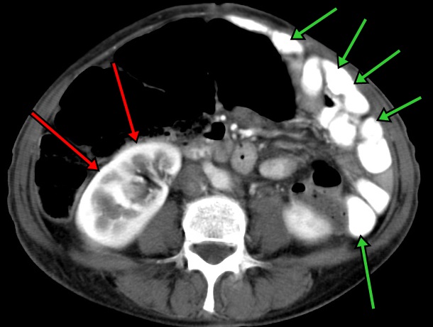
Figure 8: The effects of oral contrast on a CT scan of the abdomen.
4. Slice thickness
Take a look at these two CT scans of the chest (Figure 9). What is the difference between them? Both of them have IV contrast and both of them are showing the heart. Obviously, the scan on the right is of higher quality than that on the left, but why? The reason has to do with the thickness of the image slices. When CT scans are performed they are reconstructed into slices in the axial (transverse) plane. The axial plane is the plane that is parallel to the ground if you are standing upright. When the axial slices are stacked on top of each other the data can be used to create images in a different plane, such as when viewed from the front (the coronal plane), as in these example images. The axial slices that were used to create the coronal image on the left were 5 mm thick, whereas the axial slices used to create the image on the right were only 1 mm thick. You can see that the thick slices in the leftmost image generate structures with a very coarse appearance. If you try to 3D print an anatomic model from a scan with thick slices, your model will have a similar rough appearance. It is very important to use scans with thin slices, preferably less than 1.25 mm in thickness, when creating a model for 3D printing.
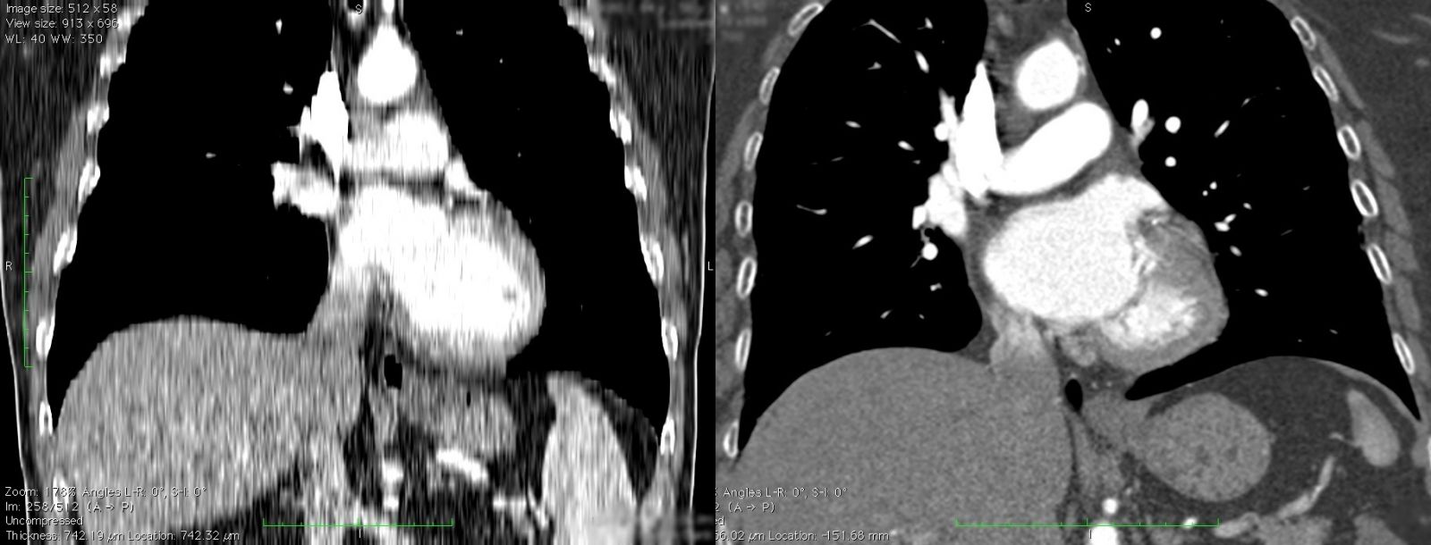
Figure 9: The effect of slice thickness on three-dimensional reconstructions.
5. Imaging artifact
Finally, take a look at these two CT scans of the face (Figure 10). What is the difference between them? The scan on the left clearly shows the teeth of the upper jaw as well as the bones of the upper cervical spine. The scan on the right however has white and black lines crisscrossing the mouth and obscuring the teeth. This type of artifact, called a beam hardening artifact, was created by metallic fillings in the teeth. When the CT scan was performed, the x-ray beam could not penetrate the metal fillings in the teeth to reach the detector. Subsequently, the scanner has no information about the x-ray appearance of the tissues along that x-ray path. When it generates an image from the x-ray data, the x-ray path with the missing information is shown as a white or a black line. The same phenomenon can be seen with any metallic object within the body, such as an artificial hip or spine fixation rods. If the scan on the right were converted to an STL file for 3D printing, the white lines would be 3D printed as well and the print would look as if sharp spikes were coming out of the mouth. Metallic objects also cause imaging artifact in MRIs. Metal on MRIs typically looks like a big black blob that obscures everything around it.
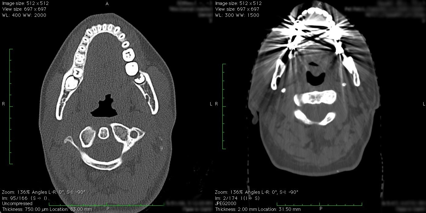
Figure 10: Two CT scans through the face and jaw. What is the difference between the two?
6. Reconstruction kernel
Take a closer look at the two CT scans of the face (Figure 10). In particular, look closely at the muscle and fat tissue of the neck. The scan on the left shows the muscle and fat tissue as being somewhat noisy. It has a granular type of appearance. On the rightmost scan however, the muscle and fat tissues appear rather smooth. This is because the two scans use a different type of reconstruction kernel. Think of the reconstruction kernel as equivalent to a sharpening or blurring function in Photoshop. The sharper kernel on the left shows the edges of the bones very clearly at the expense of causing a speckled appearance of the muscles and fat. The softer kernel on the right shows the muscle and fat more accurately, at the expense of causing the bones to have a more indistinct edge. Sharp kernels are used to make it easier to find hairline fractures and other difficult to detect abnormalities in the bones. However, for 3D printing smoother reconstruction kernels are generally best. Reconstruction kernel is primarily a factor only in CT scans.
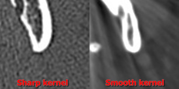
Figure 11: Zoomed image from Figure 10 of the angle of the jaw. Note how the sharp kernel has much more clearly defined bone edges, but also has a speckled, noisy appearance to the soft tissues.
Final thoughts
So there you have it. In this tutorial we have gone over the main types of imaging modalities used for 3D printing (CT, and MRI), as well as six very important factors to consider with any type of imaging scan you are thinking about using for 3D printing. There is a saying when it comes to medical 3D printing: "garbage in, garbage out." No matter what your skill level or amount of available free time, if you start the 3D printing process with a problem-laden medical scan, you will encounter nothing but frustration and probably end up with a bad 3D model assuming you can make the model at all. Do yourself a favor and carefully evaluate your medical scan prior to sinking the time and energy into creating a 3D model from it.
I hope you enjoyed this tutorial and found it helpful. If you liked this article please look see my next to tutorial on Creating a 3D Printable Medical Model in 30 Minutes Using Free Software: Osirix, Blender, and MeshMixer. Additionally, you may wish to check out the Tutorials section of the website.
Also consider registering as a member. Registration is free and allows you to post questions and comments both for blog articles and in the discussion forums. Additionally, you can download free 3D printable models from the file library.
Below are a few 3D models to download. If you wish to follow the latest medical 3D printing news, you can follow Embodi3D on various social media platforms.
Thank you very much and happy 3D printing!
Twitter: https://twitter.com/Embodi3D
Facebook: https://www.facebook.com/embodi3d
LinkedIn: https://www.linkedin.com/company/embodi3d
YouTube: http://goo.gl/O7oZ2q
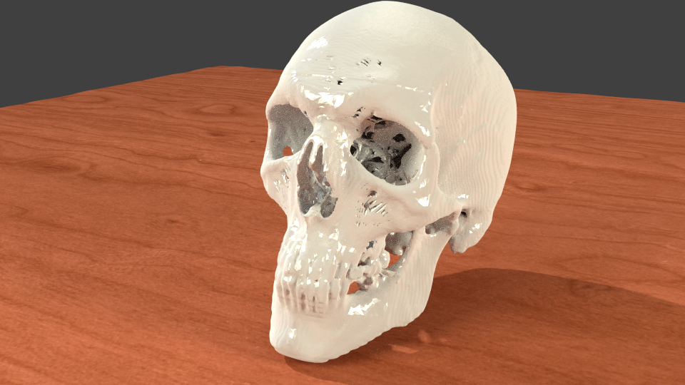
A Collection of Free Downloadable STL Skulls for you to 3D print yourself.
3D printable human heart in stackable slices, shows amazing internal anatomy.
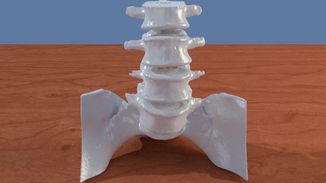
A Collection of Spine STL files to download and 3D print.


7 Comments
Recommended Comments
Create an account or sign in to comment
You need to be a member in order to leave a comment
Create an account
Sign up for a new account in our community. It's easy!
Register a new accountSign in
Already have an account? Sign in here.
Sign In Now