
Preparing CT scans for 3D printing. Cleaning and repairing STL file mesh from bones using Blender, an advanced tutorial

Entry posted by Dr. Mike ·
30,422 views

Summary: This is an advanced tutorial and assumes that you already know how to create STL files from CT scans. If you do not yet know how to do this, stay tuned, as a series of tutorials is planned on this website. Here we will use a free, open-source software package Blender to repair and correct a bony pelvis and lumbar spine model generated from a CT scan. If you would like to follow along with this tutorial, you can download the relevant Blender and STL files here, and follow along.
>>DOWNLOAD THE TUTORIAL FILES AND FOLLOW ALONG.<<
UPDATE: If you have very extensive mesh errors in your model, you can read my other medical 3D printing tutorial on how to repair mesh errors quickly using Blender.
You can watch the YouTube video for a high-yield introduction, but also read this page for additional details.
Background on the Problem
Before we dive in, let's take a moment to discuss what the medullary cavity of a bone is and why it's a problem if you're trying to 3D print bone models made from a CT scan. Bones are not solid, even though they may appear to be so. Most bones have a very hard, very dense outer layer comprised of cortical bone. This tough outer part of the bone is very hard and is what gives bones their strength. The inner core of most bones contains fatty bone marrow, and is made of much softer bone that is less dense, called spongy bone. On a CT scan you can see these two different types of bone. Take this CT scan of the pelvis, for example.
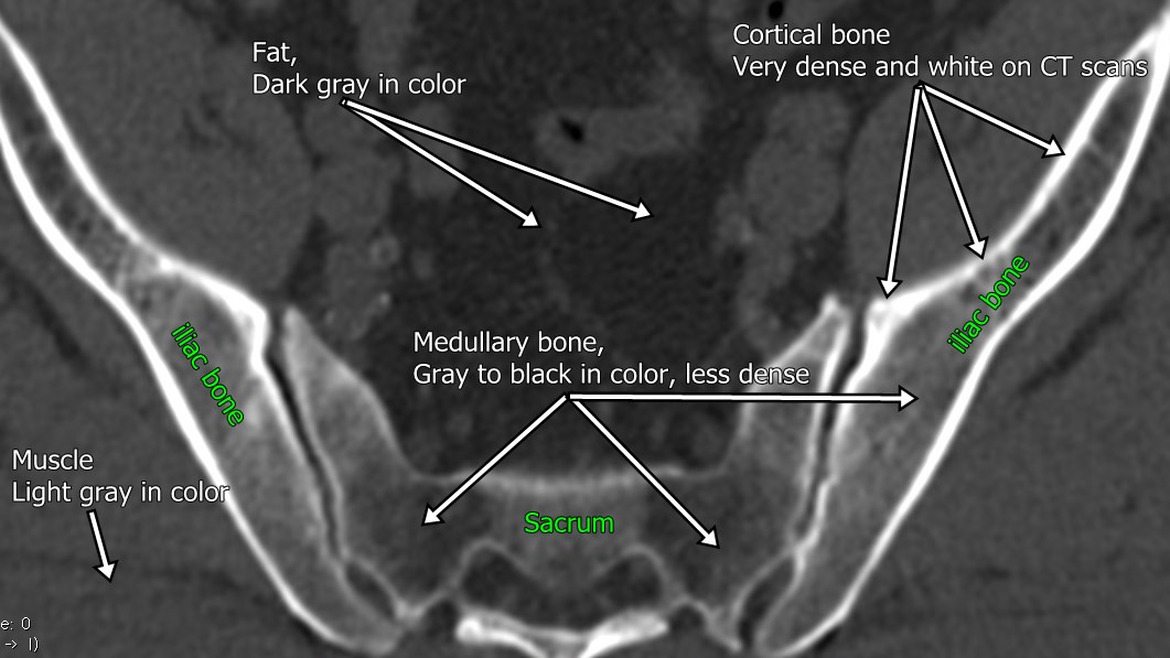
Figure 1
In the CT scan image shown in Figure 1, the hard, dense cortical bone is seen as a bright white outer surface of these pelvic bones. The white color indicates that it is very dense. The spongy bone, which is less dense and contains fatty bone marrow, can be seen in the center of the iliac bones and sacrum on this image. This type of bone is not white, but is a grayish color on a CT scan image. In some areas it is approaching black in color, which means is not very dense at all. Outside the bone we can see muscle represented by this light gray color, and intra-abdominal fat which is represented by this dark gray color.
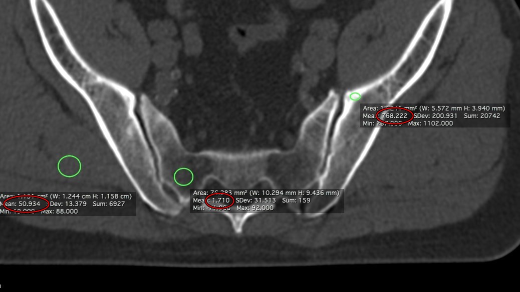
Figure 2
If we measure the density of these bones in Hounsfield units, which is the unit of density that is measured on a CT scan, we can see that the dense cortical part of the iliac bone in this image measures 768 Hounsfield units, and is shown in the rightmost red circle (Figure 2). The less dense medullary bone within the sacrum measures 1.7 Hounsfield units, as shown within the red circle in the middle. If we measure the muscle in the gluteus maximus area, this measures 51 Hounsfield units, as shown in the red circle on the left. So in this case the medullary bone is actually less dense then muscle around it. How can bone be less dense than muscle? Because it is filled with fatty bone marrow. Remember, fat floats on water, and is thus less dense than water. (What also floats on water? A duck. But that is another story...) In Figure 2, the green circles represent the area of interest that is being measured. The text and red circles represent the measurements for the those areas of interest.
The fact that medullary bone and bone marrow is not dense causes a problem when we are trying to convert CT scan data into a digital model that is 3D printable. This is because algorithms designed to select the bone from all the other stuff in the body, such as fat, muscle, air, etc), use density as a means to identify the bones. Here's an example of the 3D model of the pelvis and lumbar spine created from the CT scan we were just looking at. If you look closely at Figure 3 you can see there's a lot of internal geometry within the bones that is not desired (red circles). This extra geometry can cause problems when the file is sent to 3D printer or 3D printing service. The model may be rejected because of characteristics of this internal medullary space, for example there may be thin walls and automated quality checkers may flag the model as unprintable. Furthermore, if you try to perform certain manipulations on the mesh, such as Boolean operators, this unwanted mesh may cause these operations to fail. If we want to 3D print our bone models, it is best to get rid of extraneous and unwanted mesh.
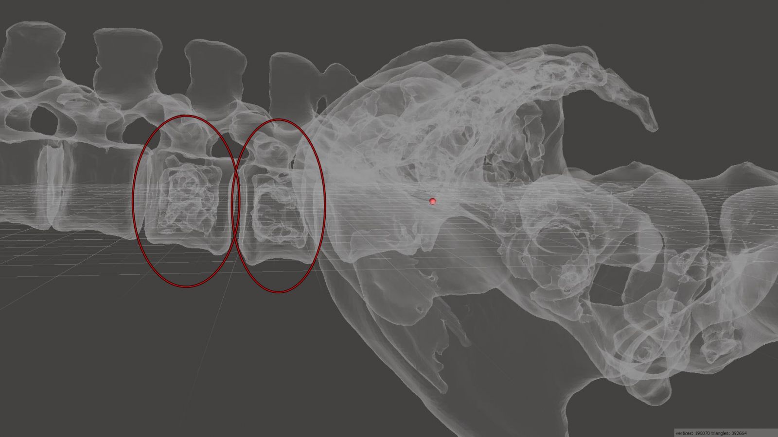
Figure 3
Getting started on cleaning your mesh in preparation for 3D printing.
1) Start by importing your STL file into Blender. If you don't have Blender, it is available for free at http://www.blender.org. Blender is available in Windows, Macintosh, and Linux versions. Be forewarned. Although Blender is powerful, it takes a little bit of time to get used to it. Be patient. Open Blender and select File -> Import -> Stl (stl) as shown in Figure 4. If you are following along with this tutorial using the tutorial files, select the "Pelvis and Lumbar spine, uncleaned.stl" file.
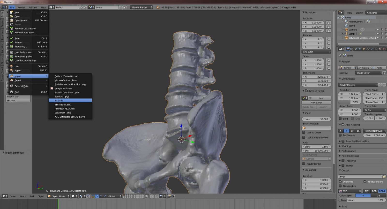
Figure 4
You will find that the mesh appears quite large. This is because Blender uses an arbitrary unit of measure for distance called a Blender Unit. The way that STL files are interpreted, one Blender unit is equivalent to 1 mm, thus the model appears quite large. Use the scroll wheel on your mouse to zoom out. If you want, you can re-size your mesh by hitting the S key.
You may also find that your mesh appears clipped, as shown in Figure 5. This is because by default Blender uses a clipping distance of 1000 by default for the view, clipping any objects in the scene too far from the camera. This is easily fixed. View the Properties bar by clicking the "+" in the upper right corner, as shown by the red circle in Figure 5. Or, you can type N to show the Properties panel. Then under View, type 100,000 in the Clip: End field, as shown in Figure 6.
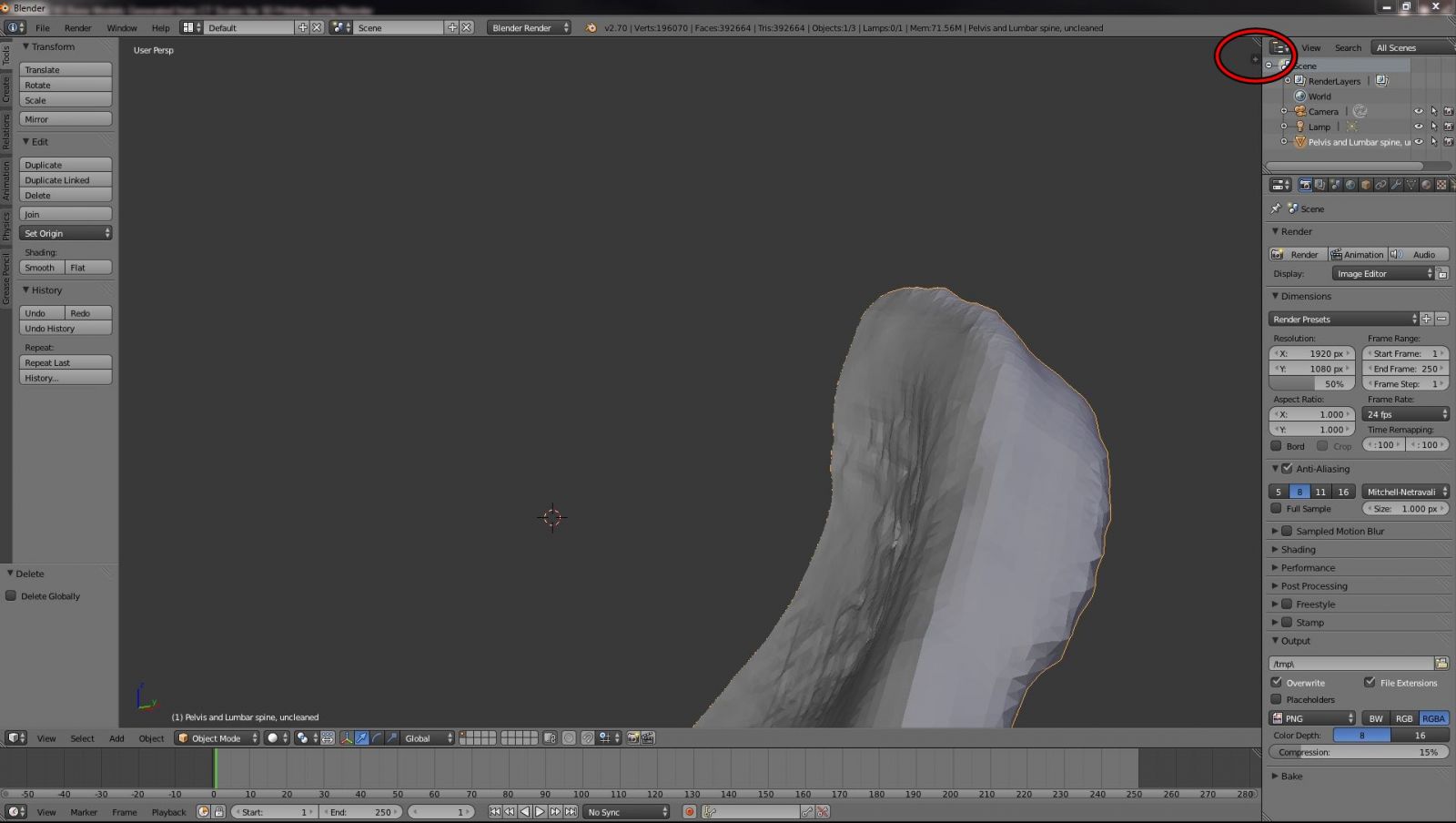
Figure 5
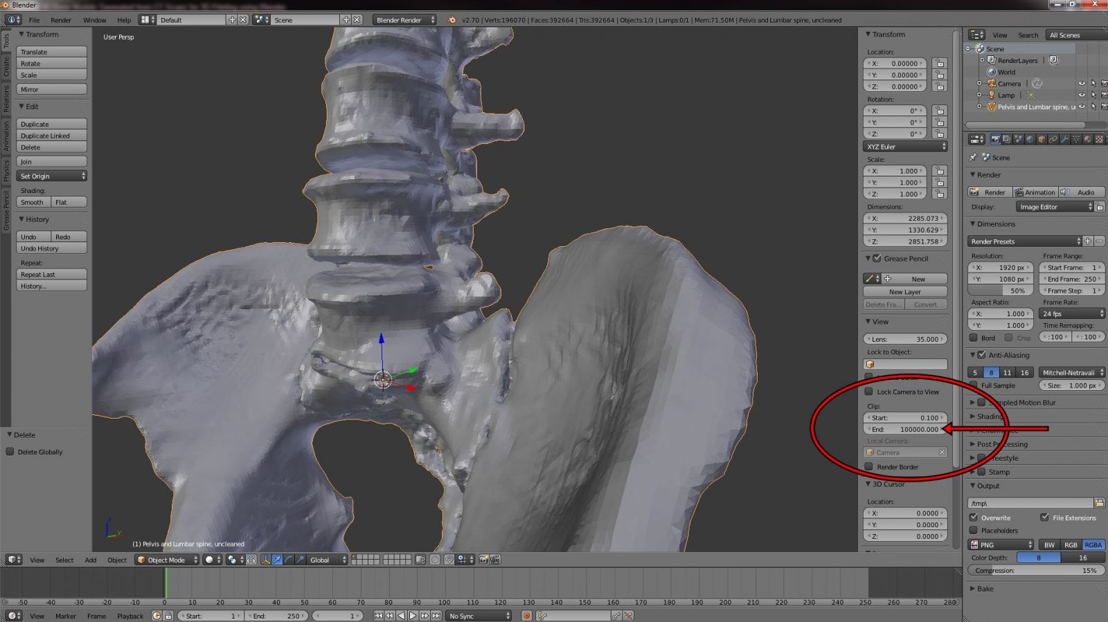
Figure 6
2) To identify where you have extraneous mesh, you must first go to Edit mode. Before doing this, make sure you have selected your model by right clicking it. The model should be surrounded by a yellow halo, which indicates that it is selected, as shown in Figure 7.
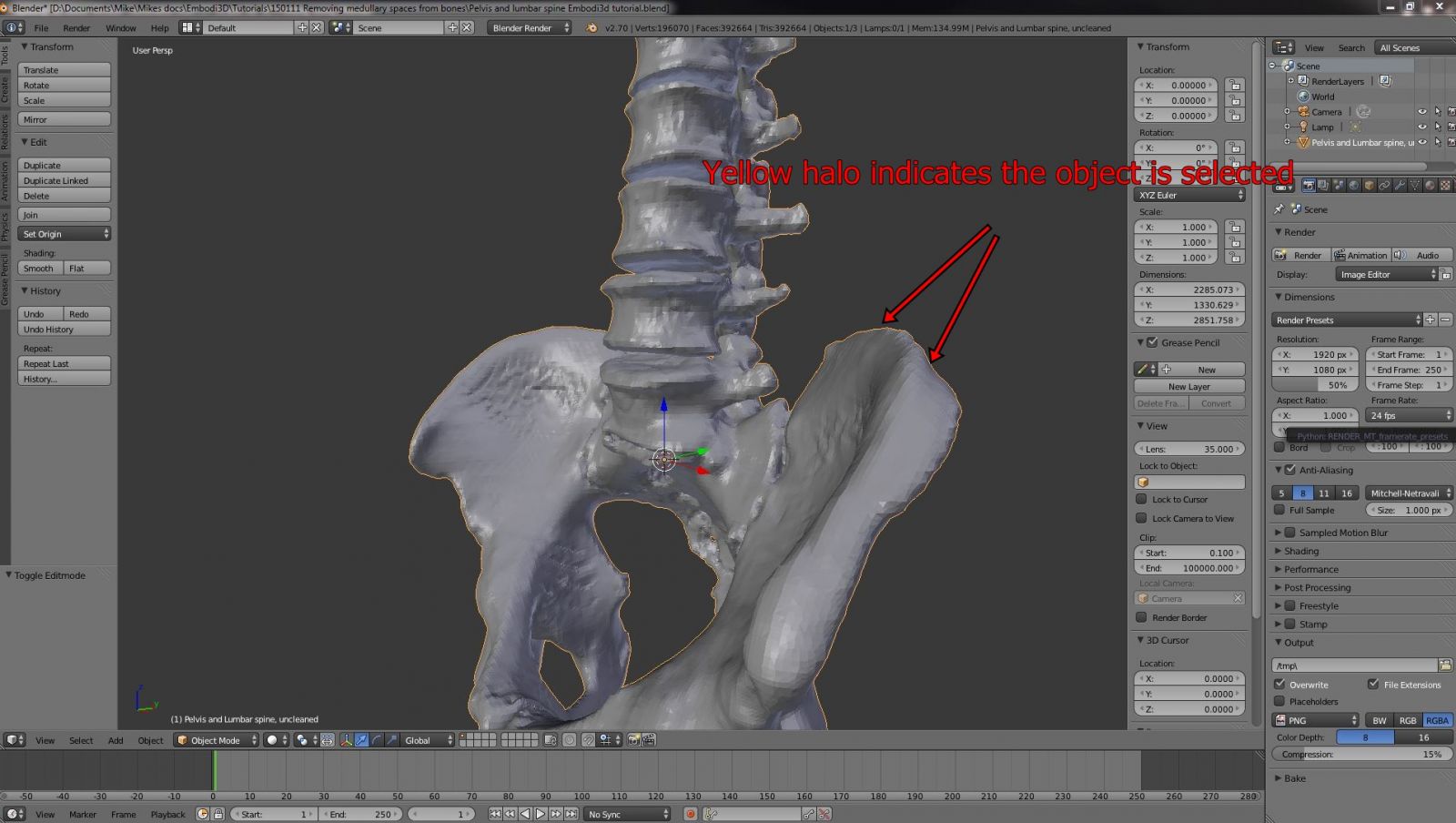
Figure 7
Enter Edit mode by hitting the Tab key, or by selecting Edit mode from the Mode button, located on the bottom left toolbar, as shown in Figure 8. Use the Z key to toggle between types of viewport shading. You can also use the viewport shading button in the bottom toolbar as shown in Figure 9. Select Wireframe viewport shading.
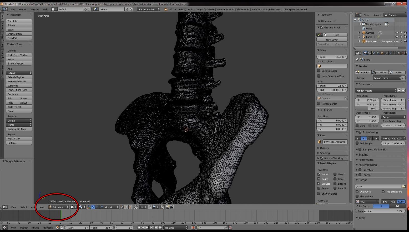
Figure 8
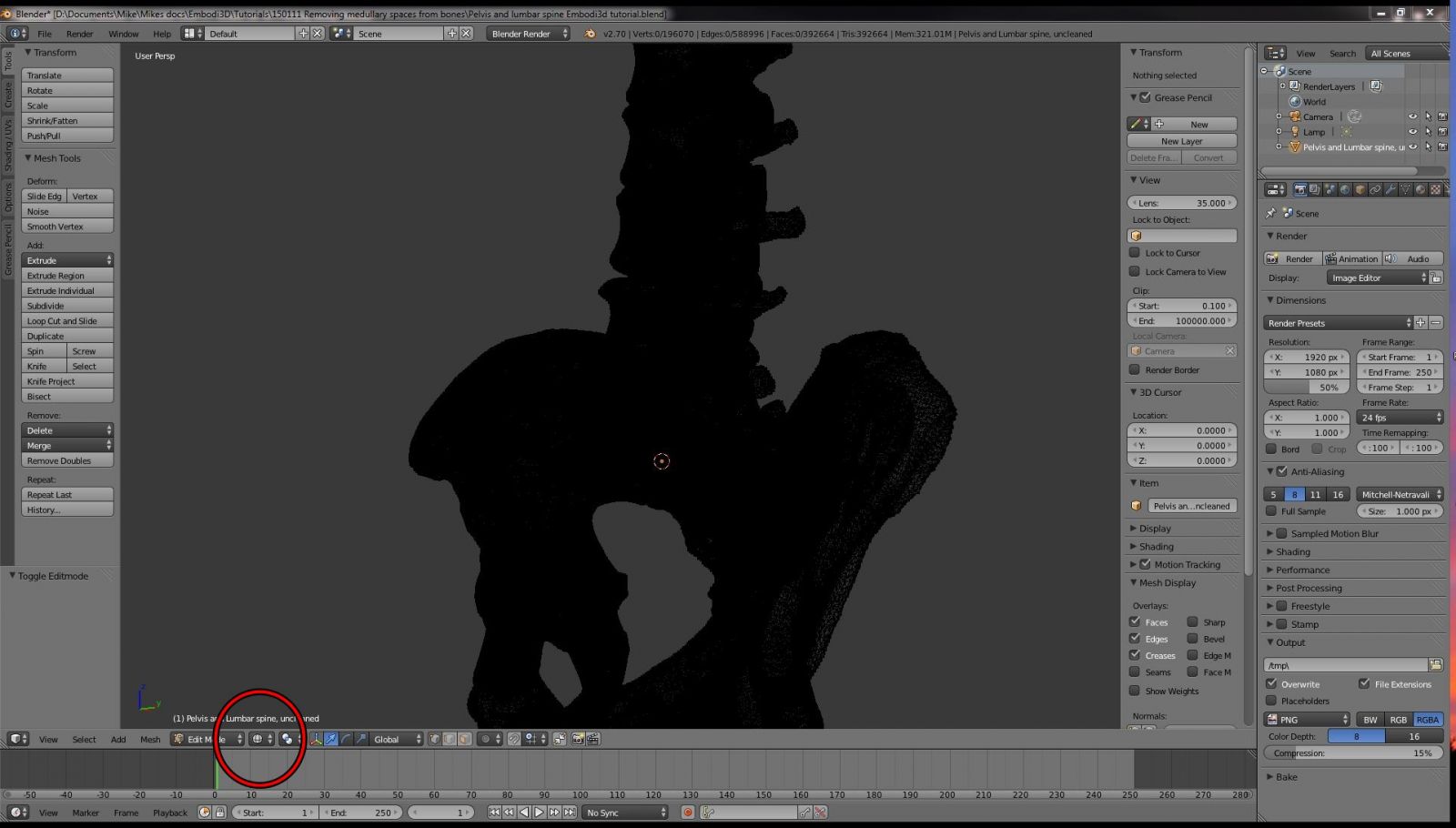
Figure 9
3) Use the scroll wheel to zoom in and out, and the middle button to pan about. Zoom into the L3 vertebral body (3rd lumbar vertebral body. If you need a refresher on lumbar anatomy, check out Wikipedia). As was shown in Figure 3, there is excessive mesh in the medullary cavity of the bone that is persistent within the model. We want to remove it.
How this extra mesh got here has to do with the original CT scan and how the surface STL model is generated from CT scan data. If you look at the original CT scan of this vertebral body, as shown in Figure 10, you can see very small perforating holes within the posterior part of the vertebral body, as shown by the red arrows. These are nutrient foramina. They are tiny holes in the bone that allow arteries to penetrate through the thick outer cortex and into the medullary cavity, supplying blood to the bone marrow. When the surface generating algorithm creates the STL file from the CT scan, it finds its way from the surface into the nutrient foramina and maps the internal medullary cavity of the bone. Essentially, the algorithm determines that the bone is hollow, and has a connecting tunnel between the surface and the hollow interior, as shown in Figure 11. This is actually true, but for the purposes of 3D printing we are not interested in extremely complex geometries within the medullary cavities of the bone. For practical purposes of 3D printing we wish the bones to be solid, even though in nature they are not.
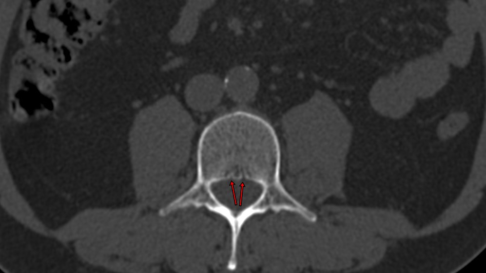
Figure 10
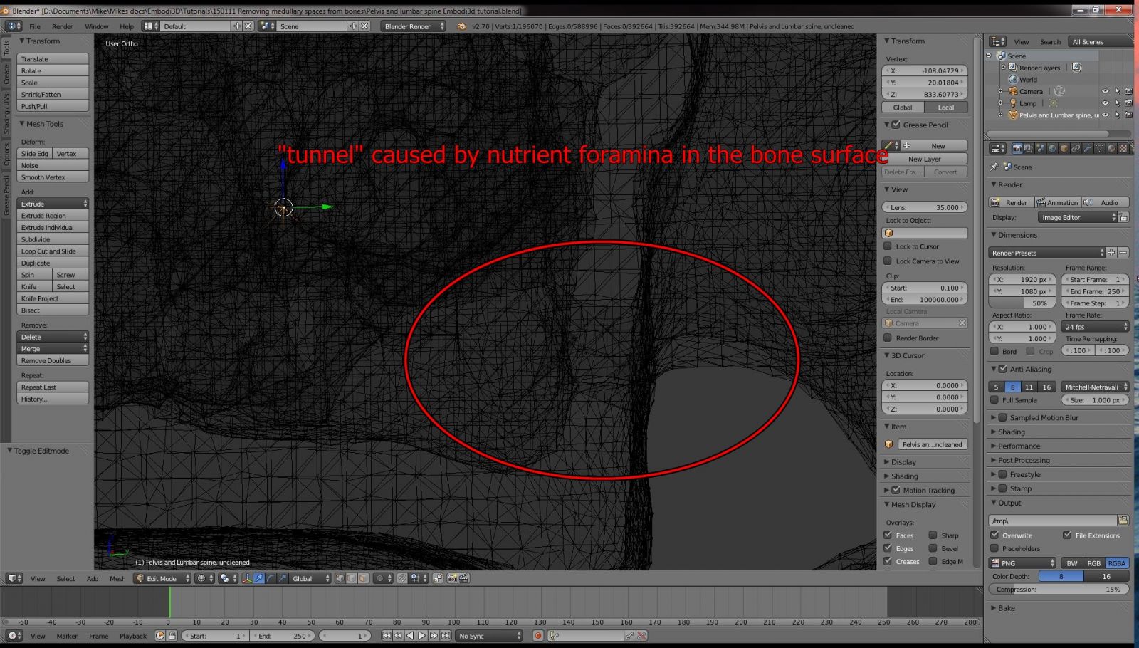
Figure 11
4) The easiest way to delete the medullary mesh is to identify where the mesh is connected to the surface via these nutrient foramina. To do this, inspect the mesh carefully using Wireframe viewport shading, which should give you an idea of where these connecting tunnels are located. Once you have identified the area, use the lasso tool by holding down the CTRL key and left clicking a loop around the area of interest, as shown in Figure 12. You must be in Wireframe viewport shading in order to make the selection. If you are in Solid viewport shading, you will only select the surface elements. Also, make sure you are in vertex selection mode. The three selection modes (Vertex, Edge, Face) are shown circled in red on the bottom toolbar in Figure 12.
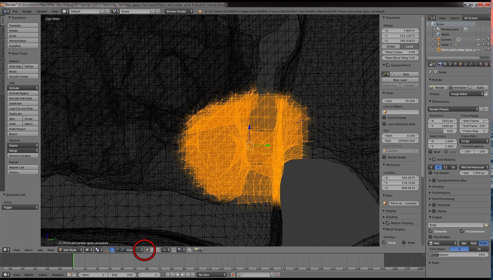
Figure 12
5) Once you have selected the mesh elements of interest, you will hide the non-selected mesh elements. This simplifies your view and also reduces the processing time needed by the computer to display the image to you in real time. With large data sets, such as those collected by CT scans, even a powerful desktop system can become very sluggish when the entire mesh is displayed and manipulated at once during editing. Hiding temporarily unneeded mesh saves a lot of time.
6) With your mesh elements of interest selected in orange as shown in Figure 12, hold down the control key and hit the "I" button. This inverts the selection, as shown in Figure 13. Next, hide the selected mesh by hitting the "H" key. You should now have a very limited amount of mesh displayed, as shown in Figure 14.
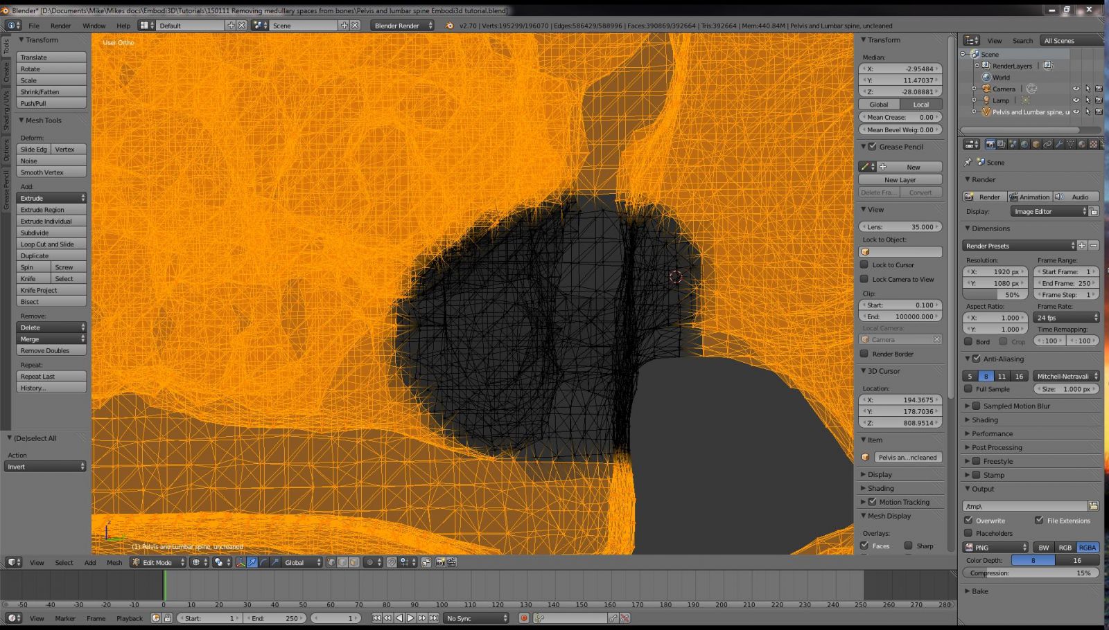
Figure 13
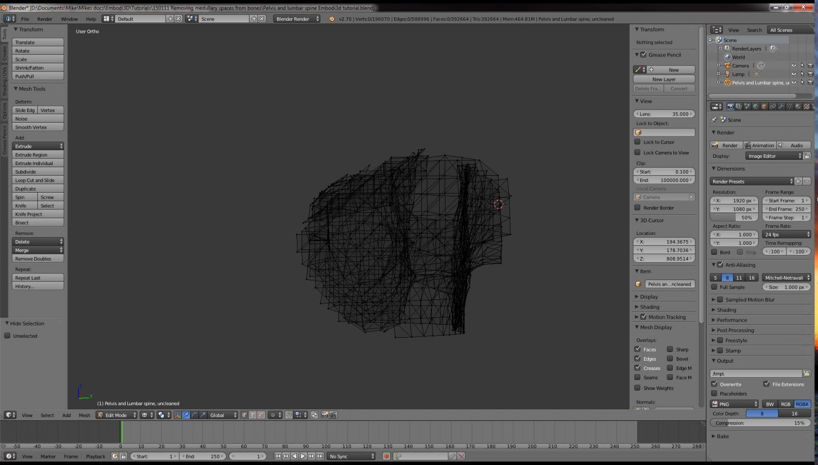
Figure 14
Rotate the mesh to a different orientation and then select your target mesh, invert the selection, and hide the inverted selection again. At this point you should have a very small amount of mesh that you are focusing on, such as that shown in Figure 15.
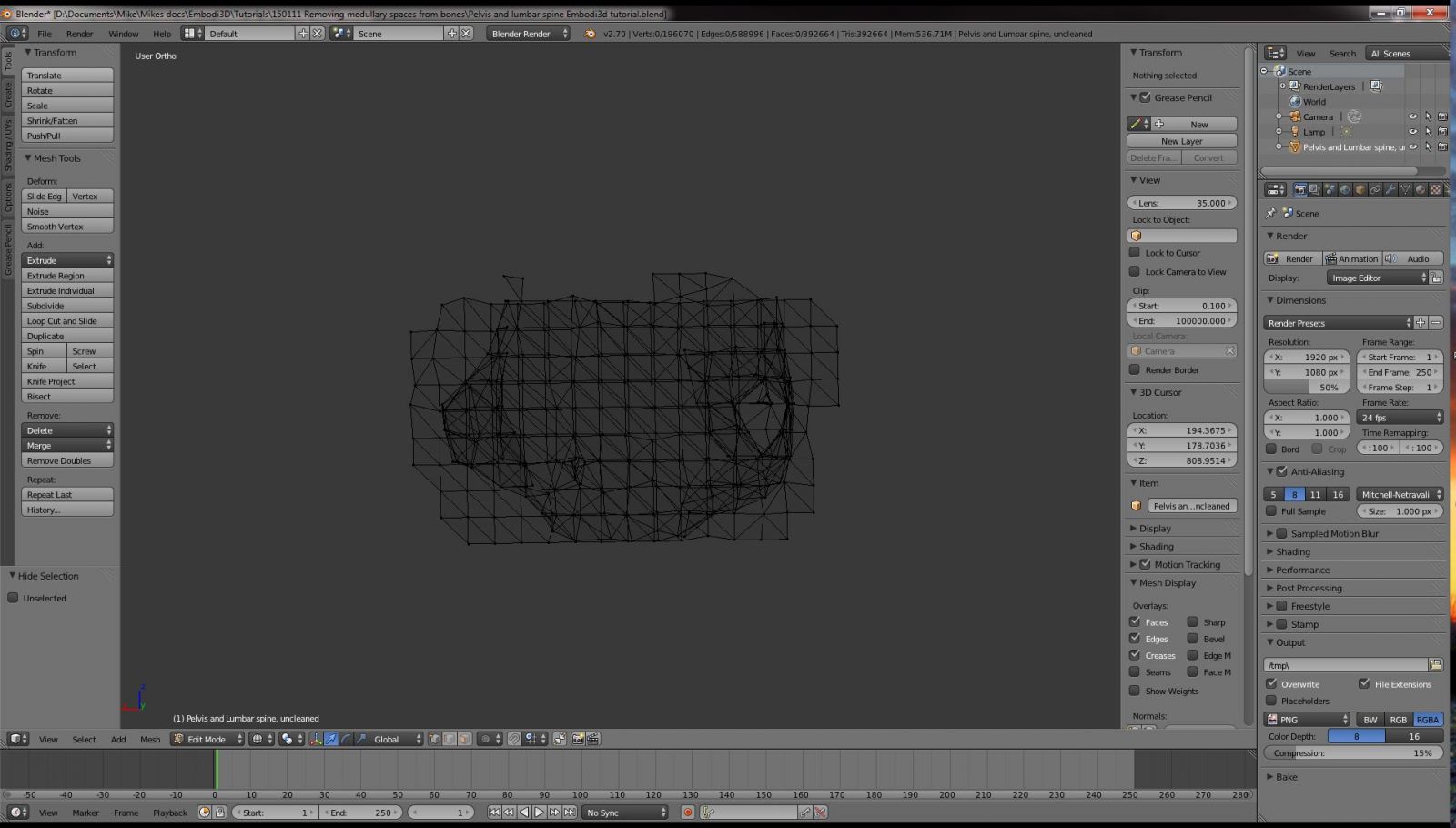
Figure 15
7) Now that your visible mesh is small enough to work with, switch back to Solid viewport shading using the viewport shading box in the lower toolbar, or by hitting the "Z" key. Zoom in and identify where the nutrient foramina are present on the surface of the bone. Go to face selection mode using the face selection button on the bottom mouth bar or by hitting CTRL-TAB-3. Using the right mouse button to select a face near the opening of the nutrient foramen. Using the CTRL key and right mouse button, select a loop of face is completely around the foramen, as shown in Figure 16. Make sure you select an entire loop of faces around the hole. You want to complete cut it away from the surface.
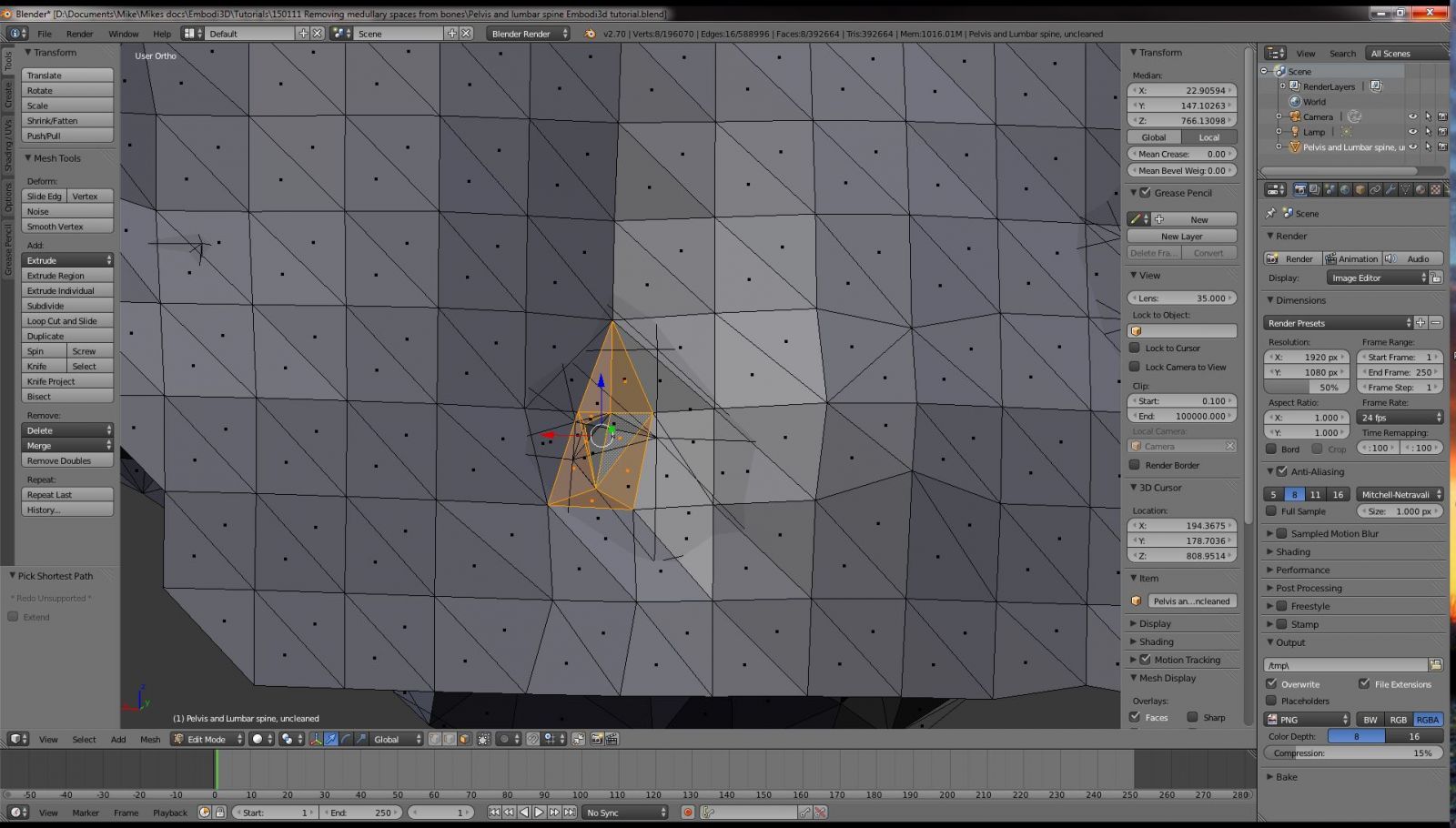
Figure 16
Now delete this selection. Hit the delete key, and select Faces (or hit the delete key followed by the F key). You should now have a hole in your mesh, and the tunnel between the surface and the medullary mesh has been cut completely. Double check to make sure there are no stray edges or face still connecting the two parts.
😎 Now we are going to close the hole. Go to Edge the selection mode using the button in the lower toolbar or by hitting CTRL-TAB-2. Holding down the ALT key, right-click on one of the edges abutting the hole. Blender should select the entire circumference of the hole, as shown in Figure 17. Next, fill in a face using the F key. A face should appear. Convert this face to triangles by hitting CTRL-T. if you want to smooth out the mesh, you can take an extra step and apply local smoothing by hitting W followed by O. Your hole should be filled in and smoothed, as shown in Figure 18.
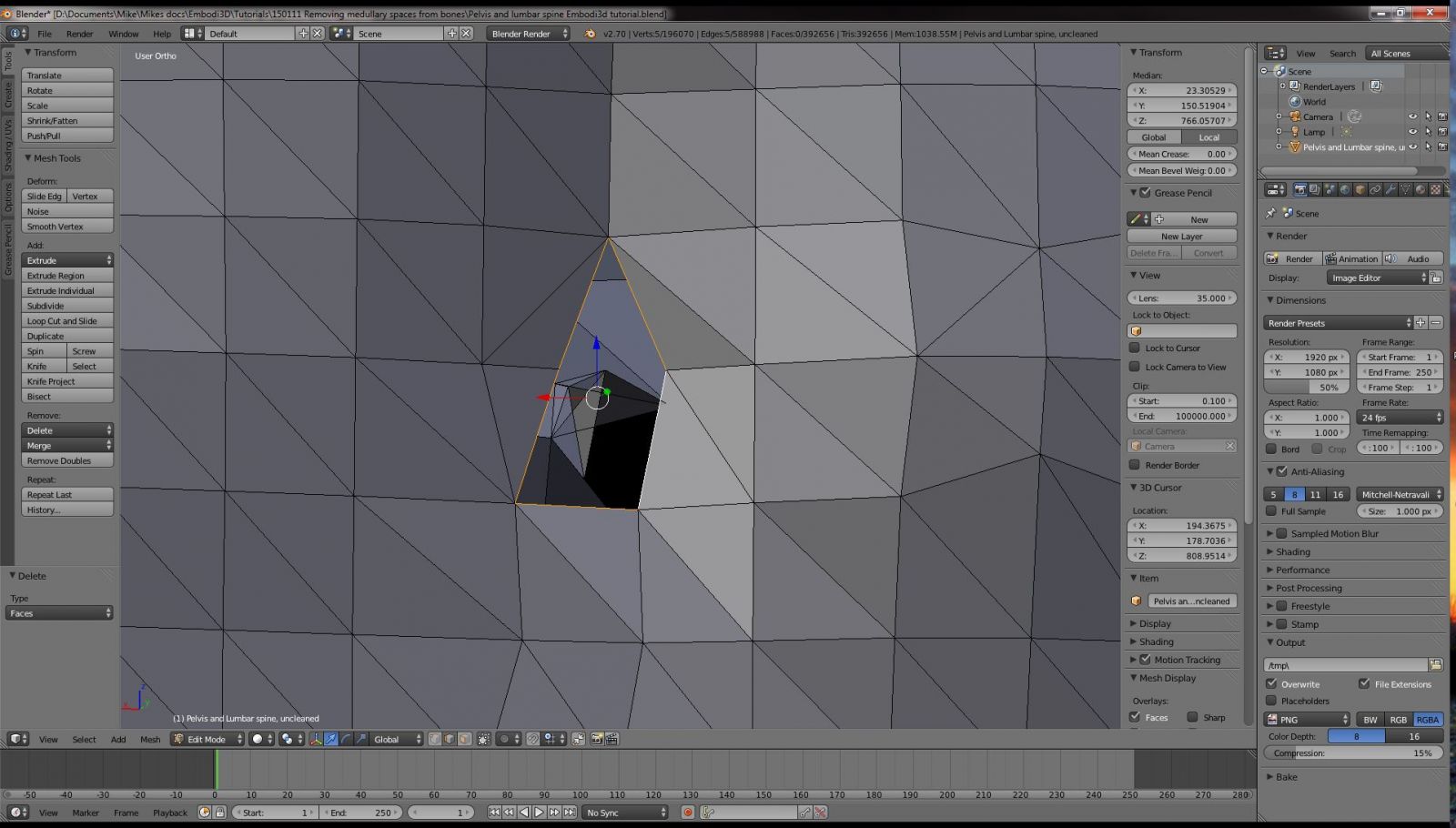
Figure 17
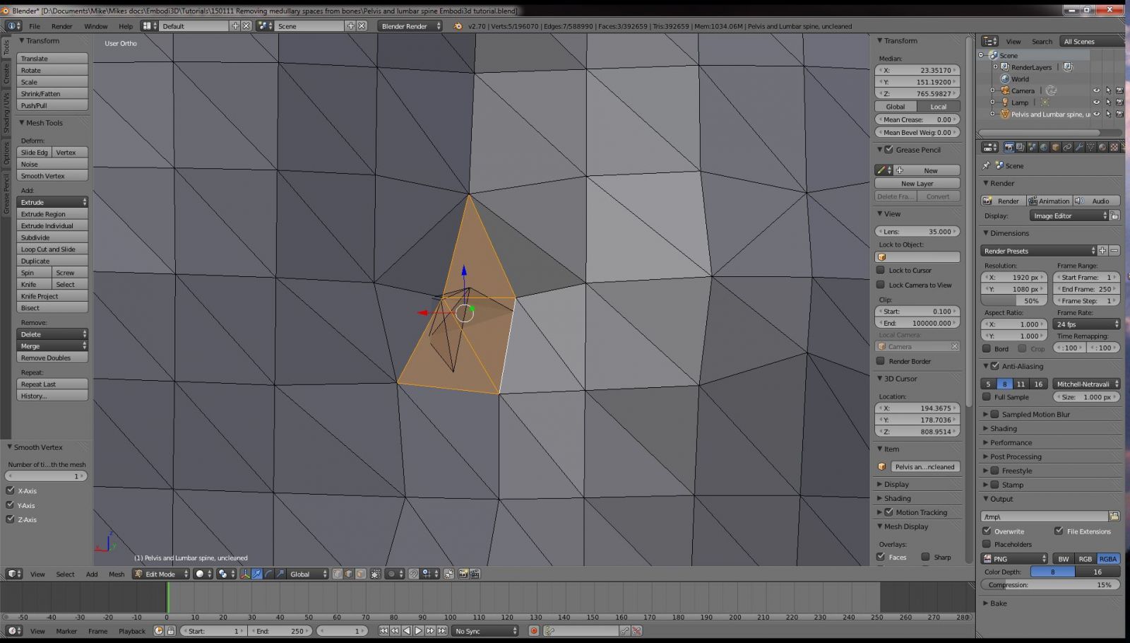
Figure 18
Repeat steps 6 through 8 for each nutrient foramen tunnel connecting the surface to the medullary cavity.
9) When you have finished making all the edits to your viewable mesh, it is time to unhide the hidden mesh that comprises the bulk of your model. Hit Alt-H to unhide all the hidden mesh. Most of it will be selected. Hit the A key to unselect all. The A key toggles between select all and select none.
10) Once you have determined that all tunnels between the surface and medullary cavity have been deleted and filled, it is time to delete the entire block of medullary mesh in one operation. Make sure you are in edit mode, with wireframe viewport shading. Using the right mouse button, select a vertex from the medullary block mesh, as shown in Figure 19.
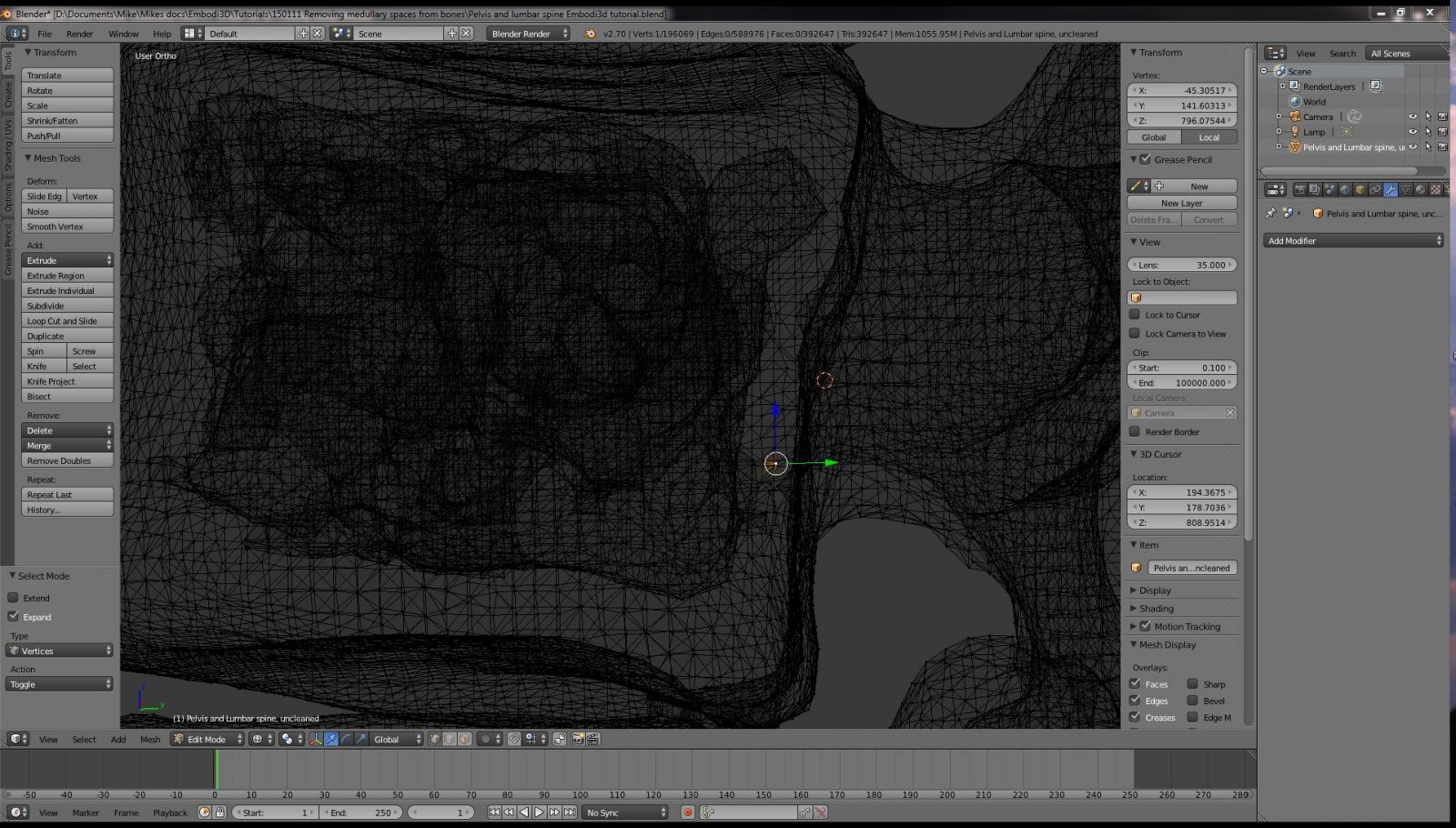
Figure 19
We are now going to select every vertex that is connected to this single vertex. Because the entire medullary mesh is disconnected from the rest of the model, the remainder of the model should not be selected. Hit the CTRL-L key to select all contiguous vertices. You should find that only the unwanted medullary mesh is selected, as shown in Figure 20. Hit the delete key, followed by "V" for vertices, and the entire block of unwanted medullary mesh will be deleted at once. Wow! That was gratifying! After all that work you have probably deleted several thousand unwanted vertices in one swoop.
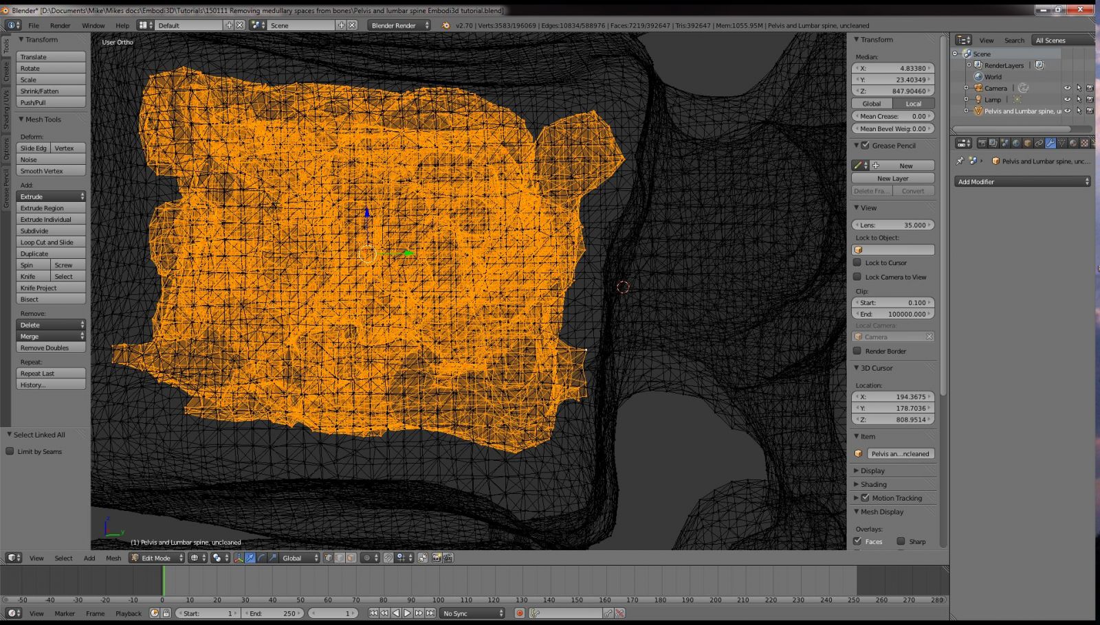
Figure 20
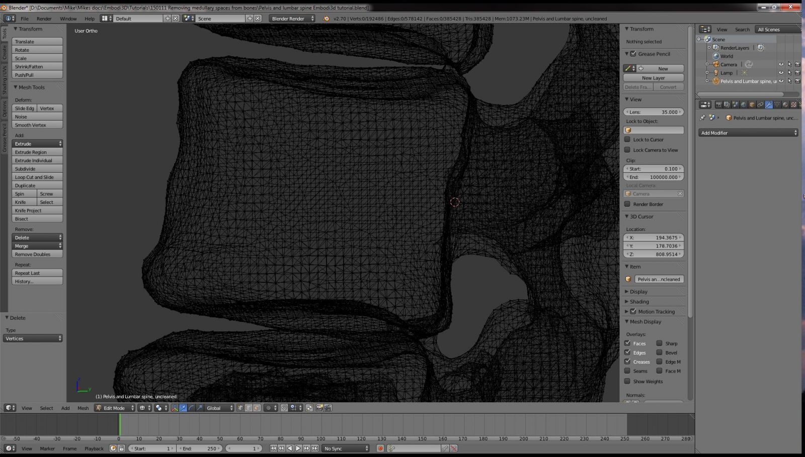
Figure 21
Your target bone, in this case L3 -- the third lumbar vertebra -- should now be free of unwanted medullary cavity mesh. You can repeat this process for each medullary cavity in your model. In the particular model that accompanies this tutorial, that would be L4, the bilateral iliac boness, sacrum, and a few other places. It can be a time-consuming process, but with practice even a complex model with tens of thousands, or millions of faces can be cleaned in a few hours.
I hope you found this tutorial helpful. If you have questions, please leave a comment below. If you are making 3D anatomic models from medical scan data, please consider sharing your creations with the Embodi3D community. Embodi3d is a community of biomedical 3D printing enthusiasts. We are all trying to help each other, and by sharing your models you can contribute greatly to the community.
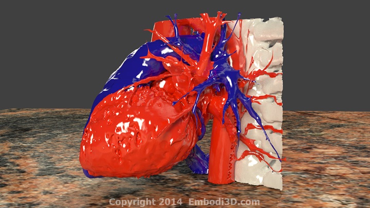
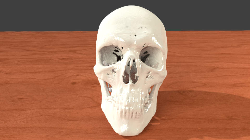
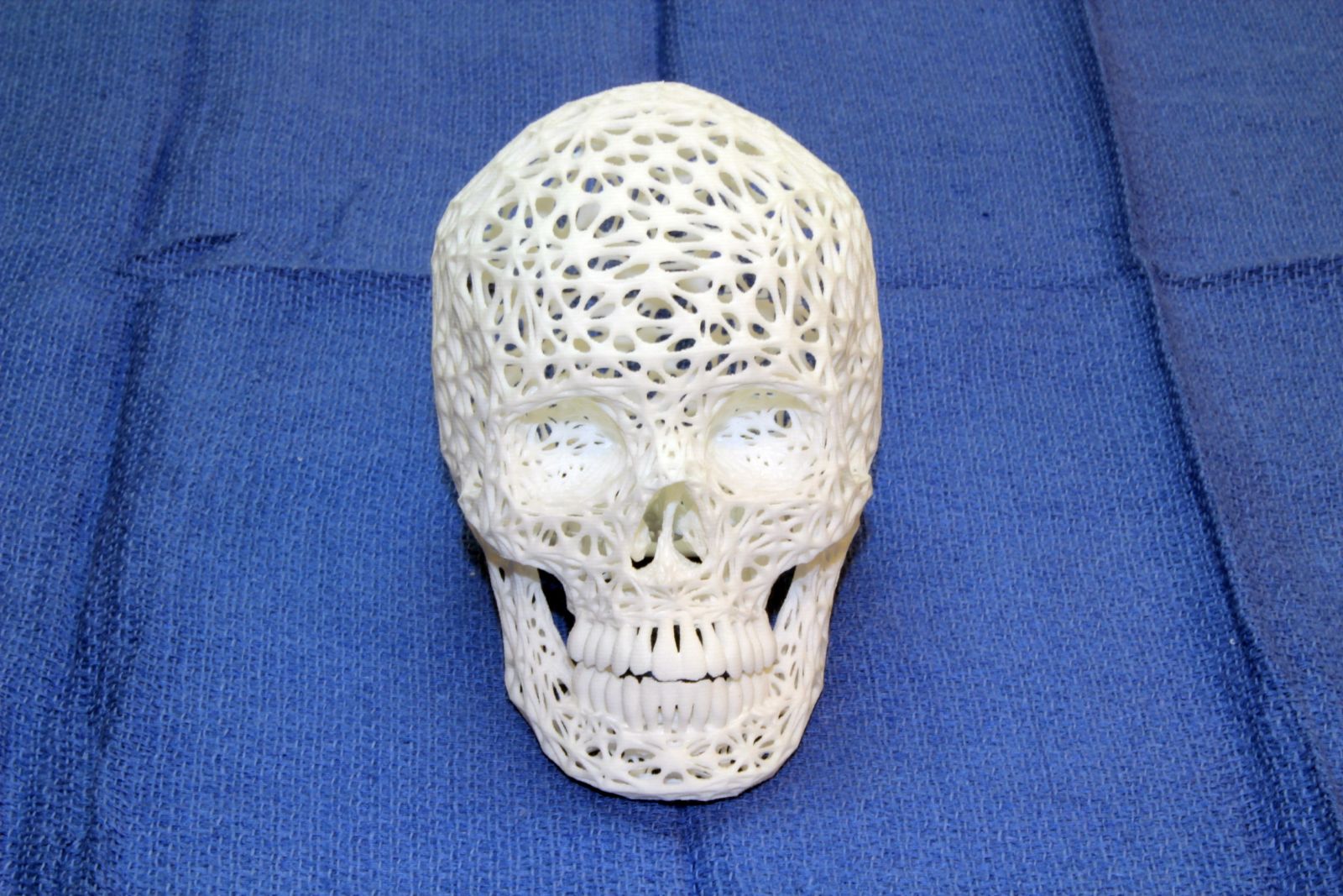
Here are a few examples of 3D printable anatomic models Embodi3D members have shared for free. Please share too!
Tweet ⇒ http://goo.gl/xuvTiv ⇐ Post to FB⇒ http://goo.gl/Ns8MuI ⇐
Twitter: https://twitter.com/Embodi3D
FB: https://www.facebook.com/embodi3d
LinkedIn: https://www.linkedin.com/company/embodi3d
YouTube: http://goo.gl/O7oZ2q


6 Comments
Recommended Comments
Create an account or sign in to comment
You need to be a member in order to leave a comment
Create an account
Sign up for a new account in our community. It's easy!
Register a new accountSign in
Already have an account? Sign in here.
Sign In Now